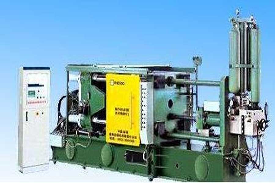
Briefly describe the structure, function and principle of the die casting machine
Die-casting machines are divided into general die-casting machines and special die-casting machines according to the scope of use; according to the clamping force, they are divided into small machines (≤4 000 kN), medium machines (4 000 kN~10 000 kN) and large machines (≥10 000 kN) ); Generally, it is mainly classified according to the machine structure and the location of the injection chamber (hereinafter referred to as the pressure chamber) and its working conditions.
1. Mold clamping mechanism:
1. Function
Mainly realize the action of closing and opening the mold, locking the mold, and ejecting the product
2. Composition
(1) Three boards
Movable seat plate, stereotyped seat plate, tail plate
(2) Corinthian Pillar
(3) Crankshaft mechanism
Long hinge, small hinge, hook hinge, and connect movable seat plate, tail plate and hydraulic cylinder for closing and opening mold
(4) Ejector mechanism
Eject the hydraulic cylinder, thimble, and fix it on the movable seat plate
(5) Die adjustment mechanism
Adjust the mold motor, gear assembly, fixed on the tail plate
(6) Lubrication system
Toggle lubrication pump, oil drain, oil pipe, diverter
3. Work characteristics
(1) Toggle mechanism
A. Strengthening effect
Through the toggle link system, the thrust of the mold clamping hydraulic cylinder can be amplified by 16 to 26 times to reduce fuel consumption, reduce the diameter of the mold clamping hydraulic cylinder, reduce the power of the pump, and achieve the same power.
B. Variable speed closing and opening movement can be realized
In the process of ejecting the mold, the moving speed of the movable mold seat plate rises from zero to the maximum quickly, and then gradually slows down, extending with the elbow until it terminates, and the clamping speed becomes zero and enters the self-locking state.
C. When the clamping is terminated, the thrust can be removed
When the clamping is tight and the toggle lever is stretched in a straight line, it will lock itself. At this time, the thrust of the clamping hydraulic cylinder can be removed. The clamping system is still in a tight state.
(2) Ejector mechanism
After the machine opens the mold, the ejection movement of the push rod and the ejector pin is realized by the relative movement of the piston rod of the ejection hydraulic cylinder. The ejection force, ejection speed and ejection time can be adjusted through the hydraulic system. Double hydraulic cylinders can be used to make the push rod evenly stressed, move smoothly, and make the ejection pin hole distribution more reasonable.
(3) Mold adjustment mechanism
The gear assembly is driven by the mold adjusting motor, so that the tail plate of the mold clamping column and the movable mold seat plate move axially along the tie rod, so as to expand or reduce the distance between the movable mold seat plates. The parameters are shown in the manual.
(4) Lubrication system
In order to reduce sports wear, proper lubricating oil must be maintained on the sports surface. It also realizes timing and quantitative lubrication. At the same time, a lubrication pump is selected to realize automatic lubrication.
2. Injection mechanism:
Function:
Hydraulic pressure of metal into the mold cavity for filling.
Composition:
injection hydraulic cylinder assembly, feed barrel, hammer head assembly, fast injection accumulator assembly, pressurized accumulator assembly.
working principle:
①The first stage slow injection movement
When the injection starts, the system hydraulic oil enters the C2 cavity through the oil circuit integrated plate, and then enters the C1 cavity through the A3 channel, thereby pushing the injection piston 2 to move to the left, realizing slow injection.
②The second stage of rapid injection movement
When the injection punch exceeds the barrel pouring port, the accumulator 3 control valve opens, and the hydraulic oil quickly enters the C1 cavity through the A1 and A3 ports. The hydraulic oil volume of the C1 cavity increases rapidly, and the injection speed increases.
③The third stage pressurization exercise
The molten metal is filled into the cavity. When it is about to terminate, the alloy liquid begins to solidify. At this time, the forward resistance of the punch increases. Under the control of the computer program, the accumulator 4 is used to control the valve to open, and it quickly enters the C3 cavity through A2, thereby promoting the increase. The pressing piston 5 and the piston rod 6 move quickly to the left. When the inner and outer conical surfaces of the piston rod 6 and the floating piston 7 are joined, A3 is cut off, so that C1 forms a closed cavity. The push of the booster piston, the piston rod, the floating piston and the pressure of the C1 and C2 chambers together make the piston 2 obtain a booster effect. .
④Slow speed, fast speed and supercharging speed can be adjusted by the control oil valve of the oil circuit board.
3. Hydraulic drive system:
Function:
Transmission of power through various hydraulic components (power components, executive components, control components, auxiliary components, working medium) and circuits to achieve various actions.
composition:
① Composition of hydraulic system
Power element-hydraulic pump
Actuator-hydraulic cylinder/hydraulic motor, realize linear and rotary motion respectively
Control element-control valve (direction, pressure, flow valve, etc.), control and adjust the flow direction, pressure and flow of the oil in the hydraulic system to meet the movement requirements of the actuator.
Auxiliary components-fuel tanks, filters, accumulators, heat exchangers, pressure gauges, pipe fittings, sealing devices, etc.
Working medium-hydraulic oil
②The composition of the hydraulic system of the die-casting machine:
Oil tanks, hydraulic pumps, mold closing hydraulic cylinders, ejection hydraulic cylinders, injection hydraulic cylinders, mold adjustment hydraulic motors, hydraulic control components, hydraulic accumulators, filters, etc.
③Hydraulic accumulator
A. Function
It is used to store a certain amount of liquid and give it out when needed to supplement the hydraulic oil of the injection mechanism and increase the fixed dynamic pressure and speed.
B. Adaptation range
It is suitable for large volume and large flow system, the temperature is between -53℃~121℃.
C. Common categories
Piston type, bladder type
④Filter
A. Function
Filter out impurities, reduce pollution to an allowable level, and ensure the normal operation of the system.
B. Common categories
Net type, line gap type, paper core type, sintered type (net type for die casting machine)
⑤ Fuel tank
A. Function
It is used to store oil to ensure sufficient and working medium for the hydraulic system. At the same time, it has heat dissipation, so that the air infiltrated into the oil can escape and deposit dirt.
B. Die-casting machine oil tank structure
Integral type: It is composed of main fuel tank, fuel tank at the feed end, and return tank, which are connected as a whole through pipelines.
⑥Air filter
A. Function
Filter hydraulic oil to prevent impurities from entering the tank, and at the same time, it has a ventilation function to balance liquid level fluctuations
B. Air filter for common oil of die-casting machine
4, safety protection:
① role
Ensure safe production and prevent accidents
② Composition
Injection area protection, clamping area protection, safety control system, emergency stop safety protection
③The protective composition and function of the shot area
Front and rear safety doors, movable mold seat plate cover, fly material baffle. Prevent splashing of molten metal during injection
④The protective composition and function of the clamping area
Front and rear safety doors, movable mold seat plate cover, tail plate cover, elbow rear cover, elbow front cover. Accidental injury occurs when preventing elbow bending and template thimble.
⑤Safety control system
Composed of front and rear safety door control systems, respectively controlled by Kyrgyzstan and PLC
⑥ Emergency stop safety protection
Set up emergency stop switch, and set up display and alarm
5. Electrical control:
① Composition
Motor, PLC control system, various electrical components, electrical wiring
②Function
Provide power to the machine and ensure that the machine works at the predetermined pressure, speed, temperature and time.
Process flow
Principle: Use correct operation methods and select reasonable process parameters to obtain excellent products.
1. Set the equipment parameters. Generally, if you are not familiar with the die casting process, adjust the mold opening time slightly to prevent splashing and hurting people due to the incomplete solidification of the workpiece when the mold is opened;
2. Select the furnace, set and heat the magnesium liquid to a suitable temperature, so that the furnace is on standby;
3. Preheat the mold and pressure chamber to a suitable temperature;
4. Pouring and injection
1) Clean alloy liquid, that is, the oxide layer on the surface cannot be injected into the pressure chamber together;
2) When injecting, select the appropriate speed and time to ensure that the end of the injection is connected to the beginning of the injection;
3) The pouring temperature should be based on the structure and wall thickness of the casting. Generally, the alloy liquid temperature should be 650~690℃, the upper temperature limit should be selected for thin-walled parts, and the lower temperature limit should be selected for thick-walled parts. On the whole, under the principle of not affecting the quality of castings, the pouring temperature is generally low;
4) When the molten metal completely enters the pressure chamber, injection should be carried out immediately, otherwise the temperature of the molten metal in the pressure chamber will drop sharply, which will affect the filling performance;
5) Be sure to pay attention to safety when injecting, the operator should close the door and let the irrelevant personnel go away;
6) The amount of molten metal spoon should be stable. Generally, the thickness of the reserved material cake should be controlled at 15~20mm. It is not only to control the final pressure transmission, but also to control the filling flow state of the alloy liquid;
7) At the beginning of production, it is best to choose slow injection to make the mold fully and evenly preheated to avoid the phenomenon of sticking mold and flying materials at the beginning of production;
5. Condensation and mold opening
The alloy liquid starts to solidify soon after being filled into the cavity, but the casting must have sufficient strength when the mold is opened to prevent damage. The mold opening time should be appropriately set according to the size, shape, and thickness of the casting.
6. Ejection and pickup
It is advisable to adjust the ejection stroke, ejector pressure and speed of the ejector pin so that the casting can remove the mold force without damaging the casting and can be easily removed from the mold with pliers.
7. Spraying of release agent
After the casting is taken out, clean the surface of the mold and the injection hammer with compressed air, and spray an appropriate amount of release agent on the surface of the cavity and core to form an extremely thin non-metallic film on the surface. The casting is demoulded. The film formation condition is that the mold surface has an appropriate temperature (250~280℃) and the release agent must be fine mist.
8. Control of mold temperature and die-casting cycle
The mold temperature has a direct relationship with the die-casting cycle. Long cycle means low mold temperature; short cycle means high mold temperature. If the mold temperature is too low, it is easy to produce long casting, cold separation, patterns, shrinkage cracks, etc., while the mold temperature is too high, the condensation speed is slow, and bubbles and mold sticking are easy to occur. Generally, the mold temperature is controlled at 200~250°C. This refers to the mold temperature after cleaning and spraying and before closing the mold.
9. Control of injection speed
Injection speed refers to the distance that the punch moves in a unit time. It is divided into three levels, namely, one-speed, two-speed, and fast injection.
1) One-speed injection refers to the speed from the start of the hammer head to the point that the hammer head seals the injection port, which can be changed by adjusting the slow injection flow rate, generally 0.1~0.3m/s;
2) Two-speed injection refers to the advancing speed at which the alloy liquid in the injection chamber is pushed to the cavity from the injection port until the alloy liquid is sent to the inner gate. The selection principle: a. Push the injected alloy liquid The heat loss before the inner gate is minimal; b. The alloy liquid will not roll, swell and entrain when it is pushed forward;
3) Fast injection refers to the speed at which the punch pushes the alloy liquid to the inner gate until the cavity is filled. The general selection principle for this level is: a. The alloy liquid must have good fluidity before filling the cavity; b. Keep the alloy liquid filling the cavity in an ideal and orderly manner, and discharge the cavity gas; c. Do not form a high-speed metal flow to wash the cavity core to avoid mold sticking. In general, it is adjusted gradually from the low limit to the high limit. In the case of not affecting the quality of the casting, a lower filling speed is appropriate. The adjustment of the starting point of the fast injection speed has a great influence on the quality of the casting;
10. Filling pressure and boost pressure
1) Filling pressure refers to the pressure required for the punch to inject the metal liquid in the pressure chamber into the inner gate within the required time during rapid injection until the cavity is filled. The filling pressure is determined by the process parameters during filling and the cross-sectional area of the inner gate. It has a great influence on the quality of the casting and lays the foundation for the realization of the final pressure (boost pressure).
2) Pressurization pressure refers to the final pressure that the punch acts on the molten metal when the molten metal fills the cavity and the injection cylinder is pressurized before it is completely solidified. The use of pressurized pressure will make the appearance and contour of the casting more clear, the internal structure of the metal is more fine, and the quality of the casting is significantly improved. But you can't blindly increase the boost pressure, otherwise it will only increase the flash of the castings and reduce the service life of the mold, thus failing to get the desired effect. Principle: The boosting flow of thick-walled parts is small, and the boosting flow of thin-walled parts is large. To adjust the pressure increase is to adjust the pressure building time, and the minimum pressure building time for a die-casting machine is certain. The pressure build-up time of Lijin magnesium alloy die-casting machine is ≤20ms.
11. In the process of testing beer products, carefully observe and analyze the products, and make corresponding parameter adjustments until the products are adjusted to the customer's satisfaction.
12. After the test beer is completed, the test mold parameter table must be filled in and brought back to the company for archives.
Link to this article: Briefly describe the structure, function and principle of the die casting machine
Reprint Statement: If there are no special instructions, all articles on this site are original. Please indicate the source for reprinting:https://www.cncmachiningptj.com/,thanks!
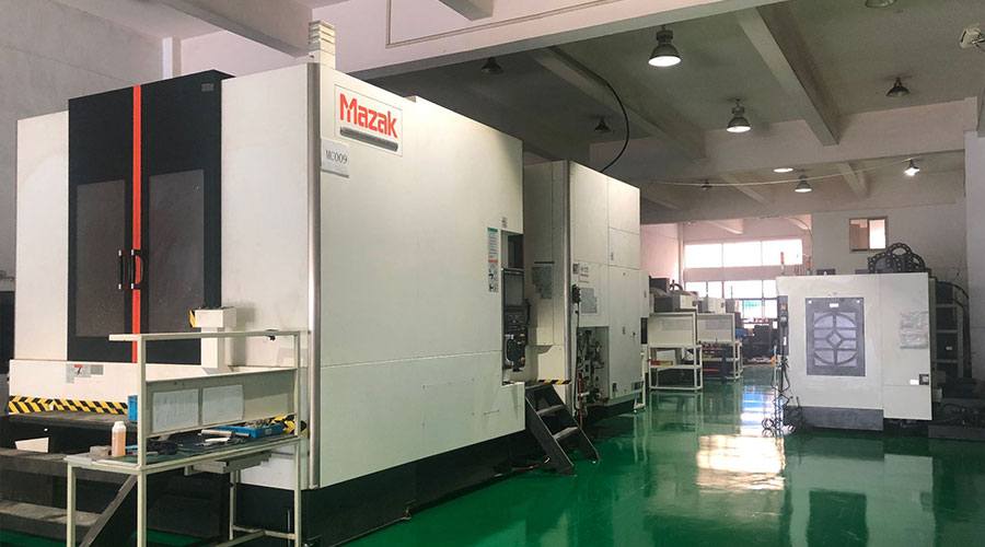 Sheet metal, beryllium, carbon steel, magnesium, 3D printing, precision CNC machining services for heavy equipment, construction, agriculture and hydraulic industries. Suitable for plastics and rare alloys machining. It can turn parts up to 15.7 inches in diameter. Processes include swiss machining,broaching, turning, milling, boring and threading. It also provides metal polishing, painting, surface grinding and shaft straightening services. The production range(include aluminum die casting and zinc die casting) is up to 50,000 pieces. Suitable for screw, coupling, bearing, pump, gearbox housing, drum dryer and rotary feed valve applications.PTJ will strategize with you to provide the most cost-effective services to help you reach your target,Welcome to Contact us ( sales@pintejin.com ) directly for your new project.
- 5 Axis Machining
- Cnc Milling
- Cnc Turning
- Machining Industries
- Machining Process
- Surface Treatment
- Metal Machining
- Plastic Machining
- Powder Metallurgy Mold
- Die Casting
- Parts Gallery
- Auto Metal Parts
- Machinery Parts
- LED Heatsink
- Building Parts
- Mobile Parts
- Medical Parts
- Electronic Parts
- Tailored Machining
- Bicycle Parts
- Aluminum Machining
- Titanium Machining
- Stainless Steel Machining
- Copper Machining
- Brass Machining
- Super Alloy Machining
- Peek Machining
- UHMW Machining
- Unilate Machining
- PA6 Machining
- PPS Machining
- Teflon Machining
- Inconel Machining
- Tool Steel Machining
- More Material

