Cnc Turning Case Studies Of Stainless Steel Low Temperature Ammonia Pump Slender Shaft
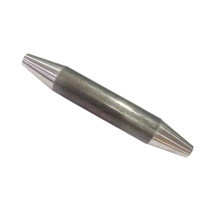
The turning of the stainless steel slender shaft of the low temperature ammonia pump uses the CY6140-B horizontal lathe to complete the turning of the stainless steel slender shaft of the ammonia pump in the coalification area of the ironworks, which meets the customer's requirements and ensures the normal operation of the equipment.
The machining operation area of the Mechanical Engineering Department of the Construction Branch mainly undertakes the task of processing parts for the main plant of Panzhihua Iron and Steel Vanadium Company. The processed parts are relatively sporadic, complex and diversified. Generally, they are not mass-produced and processed. There are all kinds of processed parts. The pump shaft of the ammonia pump in the coal chemical area of the iron plant is one of them. Due to the corrosive nature of ammonia, 316L stainless steel is selected for the shaft of the pump to extend its service life, with a length of 1 220mm. Generally, when the ratio of length to diameter L/D>25, the shaft is called a slender shaft. Because the cutting process is performed on a horizontal lathe, it is necessary to fully consider whether the horizontal lathe can achieve the machining accuracy, whether the coaxiality and circular runout of the processed stainless steel slender shaft can meet the requirements, and whether the running time in the pump body can meet the production Overhaul period.
1. Difficulty analysis of stainless steel slender shaft turning process
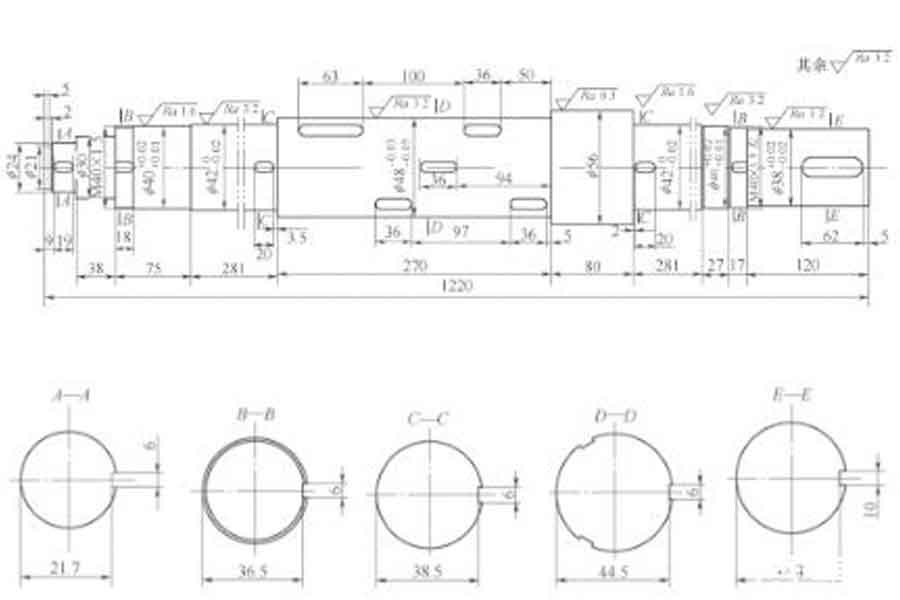
- 1) When the slender shaft (see Figure 1) rotates on a lathe, it is easy to bend and vibrate under the action of centrifugal force and gravity, and has poor rigidity.
- 2) The workpiece will be bent and deformed under the action of cutting force. Improper use of the tool holder will cause problems such as taper, rhombus, drum shape, polygon and slub shape, which will not meet the accuracy requirements of the workpiece.
- 3) In the cutting process, heat will also produce deformation, especially stainless steel materials have poor thermal conductivity, high plasticity, and high toughness. The corresponding cutting force and cutting heat are also large, forming another processing difficulty.
- 4) Due to the low thermal conductivity of stainless steel, the turning tool is easy to wear, and the adhesion is strong. Chips are prone to build up on the tool tip during turning, and the workpiece is not easy to obtain good surface roughness, so full consideration should be given to the selection of tools.
2. The Solution Of Cnc Turning Stainless Steel Low Temperature Ammonia Pump Slender Shaft
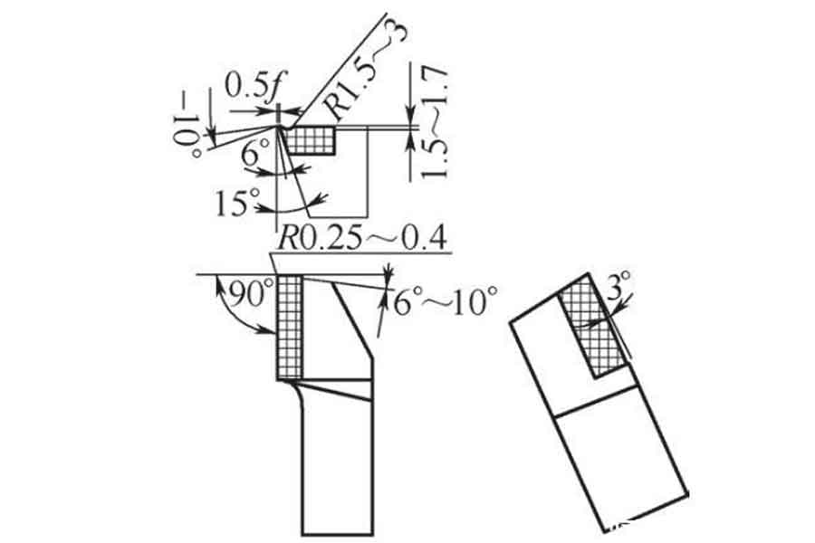
- (1) The tool is made of YG532 and YG813 hard alloy materials. When processing stainless steel, the geometry of the cutting part of the tool is considered from the rake angle, the back angle and the chip geometry. For smooth chip removal, a chip breaker with a radius of 1.5 to 3 mm should be ground, and the rake angle of 15° to 20° is the most appropriate. In terms of cutting heat generation and heat dissipation, increasing the rake angle can reduce the cutting heat generation, and the cutting temperature will not be too high. In the initial machining, the cutting edge strength of the cutting tool is required to be high, and a smaller relief angle should be adopted. In semi-finishing machining, tool wear mainly occurs on the cutting edge and the relief angle, and the relief angle is 6°~8°. When finishing, a large blade inclination angle should be used, and the size and direction of the blade inclination angle determine the direction of chip flow. In order to control the generation of built-up edge, it is necessary to improve the quality of the surface of the part, and the blade inclination angle is preferably 3°~5°. The structure of the external circular knife is shown in Figure 2.
- Requirements for the toolholder material: When processing stainless steel, due to the excessive cutting force, the toolholder must have sufficient strength and rigidity to avoid chattering during the cutting process, and quenched and tempered 45 steel can be used. Both the triangular thread turning tool and the grooving tool are made of powder metallurgy materials, cobalt-containing high-speed steel or aluminum-containing super-hard high-speed steel, for low-speed turning. The best choice for chip flute radius is 4~6mm and width 2mm, so that chip evacuation is smoother and resistance is smaller. The thread cutter should use the thread template, sharpen it and inspect it at the same time, to reach an angle of 60°.
- (2) Reasonable use of center frame and three-jaw tool holder. When the center frame is supported at the middle position of the workpiece, the L/D value is reduced by half, and the rigidity of the workpiece is increased several times. Fixing the tool holder on the large carriage can follow the movement of the turning tool, offset the radial cutting force, increase the rigidity of the workpiece, and reduce the deformation, thereby improving the shape accuracy of the slender shaft and reducing the surface roughness value. Generally speaking, the follower tool holder has 2 claws. In actual use, the workpiece itself has a downward gravity, which causes the workpiece to inevitably bend. Therefore, during turning, the workpiece tends to vibrate due to the centrifugal force momentarily leaving and contacting the supporting claws. If the workpiece is supported by the follower tool holder with 3 supporting claws, the turning tool has a top force, so that the workpiece cannot move up and down, left and right, the turning process is very stable, and it is not prone to vibration, and the use effect is better than the follower tool with 2 supporting claws shelf. The support claws of the center frame and the follower should be adjusted properly. Too loose will not have the effect of rigidity. Too tight will affect the shape accuracy of the workpiece. The workpiece will be "bamboo-shaped" during turning. Check the tightness of the support claws frequently and make necessary adjustments.
- (3) Consideration of thermal deformation factors of cutting shaft workpieces When machining slender shafts, the cutting fluid should be supplied sufficiently to reduce the temperature of the workpiece. Because the workpiece is long, the coefficient of linear expansion is large, and small temperature changes can cause it to deform and elongate under heating, it cannot be processed with a fixed center, otherwise it will limit the thermal elongation of the workpiece, causing the workpiece to bend and deform, and it cannot be turned normally. The elastic rotary center is adopted. When the workpiece is extended, the center automatically retreats to compensate for the thermal deformation and elongation of the workpiece.
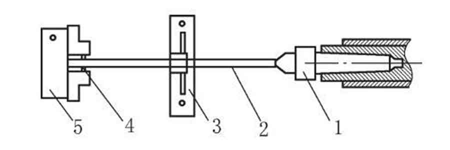
- (4) Clamping method The material of the stainless steel slender shaft of the ammonia pump is 316L, which is delivered by the manufacturer, with a diameter of 60mm. In order to prevent contact between the tool holder and the chuck during the machining process, after measurement and calculation, the length of the blank is about 350mm longer than the actual length of the workpiece, so as to meet the normal use of the tool holder. This slender shaft adopts the clamping method of one clamp and one top, and the influence of repeated positioning should be considered during the clamping process. Therefore, we have prepared 3 spring steel bars with a length of 20mm and a diameter of 6mm with a harder material. Between each jaw of the core chuck and the contact part of the workpiece, the clamping contact part is in line contact, which can well eliminate the negative influence of repeated positioning, as shown in Figure 3.
3. Process arrangement and turning process
- 1) Turn the end face of the blank first, and punch a φ3mm center hole. Install the tool post to prepare for rough turning, the speed is 180r/min, the amount of tool is 2mm, the feed rate is 0.1mm/r, when turning 45-60mm in the direction of the chuck, the supporting claw of the tool post will be in contact with the machined surface of the workpiece , Install the outer claw first, then the side claw, and then the lower claw, the tightness is moderate. The blank is turned in two times to the maximum diameter of 57mm of the workpiece. After semi-finishing and finishing, it reaches the maximum diameter of 56mm in Figure 1. During these two turning processes, it is necessary to detect whether there is a big head or not, and adjust the tailstock to control it.
- 2) Place the center frame on the shaft step of the φ57mm, 80mm long workpiece, that is, process it in two stages, so that the rigidity of the workpiece can be increased several times. When using the center frame, the strength of the three supporting claws should be appropriate to allow the three supporting claws to run-in with the machined surface of the workpiece, so that the contact surface of the supporting claws is smooth and tidy, and lubricating and cooling with oil.
- 3) Place the end of the workpiece with the smaller diameter on the tailstock end (that is, the right-hand threaded end of the workpiece, called the right end), and the end with the larger diameter of the workpiece on the chuck end (that is, the left-hand threaded end of the workpiece, called the left end) ), turning right and then left. When turning the right end, the center frame is supported on the φ56mm step of the workpiece; when turning the left end, the center frame is placed at the right end of the φ48mm step that has been rough turned on the right end, and the turning tool must be installed on the right side of the tool holder, so that the carriage and the center frame After the measurement, it will not be blocked. During rough machining, semi-finishing turning, finishing turning and turning the left and right ends of the thread, the center frame must be exchanged and supported with the carriage at the two parts of the workpiece to ensure normal turning.
- 4) Using a 90° offset tool, rough turning each step at the right end to above the actual size, leaving a margin of 1mm, and then semi-finishing and finishing, which can be measured with a vernier caliper. The length of each step has a fine turning margin of 0.5mm, which can be measured with a steel ruler and a depth vernier caliper. When rough turning the left end, install the 90° anti-offset tool on the right side of the tool post for reverse feed turning, leaving a 1mm semi-finishing and finishing allowance for the outer diameter, and repeat turning each step until all the steps of the workpiece are located. Rough turning of diameter and length is completed.
- 5) Semi-finished car. You can semi-finish either end first. In order to save time, do not reverse the center frame and carriage, and directly start semi-finishing the left end of the workpiece. In semi-finish turning, the speed can be increased to 240r/min, the cutting amount is about 0.6mm, and the feed rate is 0.1mm/r. Adjust the support strength of the center frame and the follower to the best, so that there is no vibration during the turning process. In this way, the semi-finishing turning of each step is carried out, leaving a margin of 0.4mm for fine turning, and at the same time, finishing the workpiece step φ56mm to the free tolerance, and then finishing the length of each step to the required size and measuring with a depth vernier caliper. Use the same turning method to semi-finish the right end of the workpiece.
- 6) Generally speaking, the processing of slender shaft grooves and threads should be placed between semi-finishing and finishing, in order to prevent the workpiece from vibrating after finishing, so as not to affect the coaxiality of the workpiece. First cut the thread undercut and circlip groove on the right end of the workpiece, and then cut the thread undercut and empty groove on the left end of the workpiece. In order to reduce the vibration, the speed is set to 70r/min, and then the nominal size of the two threads is fine-cut to φ40 (-0.05, -0.10) mm, and a triangular thread turning tool is installed. Because the thread pitch is small, the center frame is used to support the φ56mm, and the two M40×1.5mm left and right-hand threads of the workpiece are turned by the transverse feed method. Thread size requirements: d2=D2=d-0.649 5p=40-0.649 5×1.5=39.026 (mm), h1=0.541 3p=0.541 3×1.5=0.8 1 2 (mm), d1=D1=d-1.082 5p =40-1.082 5×1.5=38.376 25 (mm).
- 7) After finishing turning, check the tightness of the center frame once again, and cool the whole workpiece to prevent the size change after finishing turning. The other angles of the fine turning tool remain unchanged. The tip of the tool is ground to an arc angle of R0.1~R0.2mm, the speed is increased to 320r/min, and the feed rate is 0.05mm/r, which can improve the surface quality of the workpiece, Use an outside micrometer to measure when driving. When the outer diameter of each step is fine-turned, it can be turned several times if it is not in place at one time until the tolerance reaches the size requirement. After finishing turning the left and right ends of the workpiece, use a file to chamfer and deburr. When cutting off, the follower holder is no longer used, so that the center part of the center frame supporting the workpiece is cut at a low speed, and the margin is left to be cut with a hacksaw. After inspection, the size of each part of the workpiece meets the requirements.
4. Conclusion
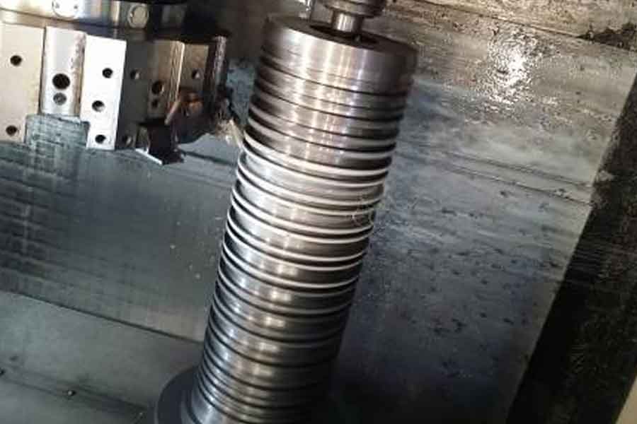
The stainless steel slender shaft is indispensable in the production of ammonia in the coalification area of the iron plant. For our department, it is difficult to turn the stainless steel slender shaft without CNC machine tools and grinders. Through continuous exploration and accumulation of experience, we have worked out targeted solutions, processed qualified products, and guaranteed the various processing accuracy requirements of the stainless steel slender shaft. After use, we have been highly praised by customers.
Link to this article: Cnc Turning Case Studies Of Stainless Steel Low Temperature Ammonia Pump Slender Shaft
Reprint Statement: If there are no special instructions, all articles on this site are original. Please indicate the source for reprinting:https://www.cncmachiningptj.com/,thanks!
 PTJ® provides a full range of Custom Precision cnc machining china services.ISO 9001:2015 &AS-9100 certified. 3, 4 and 5-axis rapid precision CNC machining services including milling, sheet metal to customer specifications,Capable of metal & plastic machined parts with +/-0.005 mm tolerance.Secondary services include CNC and conventional grinding, laser cutting,drilling,die casting,sheet metal and stamping.Providing prototypes, full production runs, technical support and full inspection.Serves the automotive, aerospace, mold&fixture,led lighting,medical,bicycle, and consumer electronics industries. On-time delivery.Tell us a little about your project’s budget and expected delivery time. We will strategize with you to provide the most cost-effective services to help you reach your target,Welcome to Contact us ( sales@pintejin.com ) directly for your new project.
- 5 Axis Machining
- Cnc Milling
- Cnc Turning
- Machining Industries
- Machining Process
- Surface Treatment
- Metal Machining
- Plastic Machining
- Powder Metallurgy Mold
- Die Casting
- Parts Gallery
- Auto Metal Parts
- Machinery Parts
- LED Heatsink
- Building Parts
- Mobile Parts
- Medical Parts
- Electronic Parts
- Tailored Machining
- Bicycle Parts
- Aluminum Machining
- Titanium Machining
- Stainless Steel Machining
- Copper Machining
- Brass Machining
- Super Alloy Machining
- Peek Machining
- UHMW Machining
- Unilate Machining
- PA6 Machining
- PPS Machining
- Teflon Machining
- Inconel Machining
- Tool Steel Machining
- More Material

