Workpiece installation and its fixtures
Workpiece Installation And Its Fixtures
|
Direct mounting method The workpiece is directly placed on the machine table or general fixture (such as standard accessories such as three-jaw chuck, four-jaw chuck, flat-nose pliers, electromagnetic chuck, etc.), and sometimes it is clamped without finding another correct, for example The three-jaw chuck or electromagnetic chuck is used to install the workpiece; sometimes it is necessary to align the workpiece according to a certain surface or scribe line on the workpiece, and then clamp it, such as installing the workpiece on the four-jaw chuck or on the machine table. |
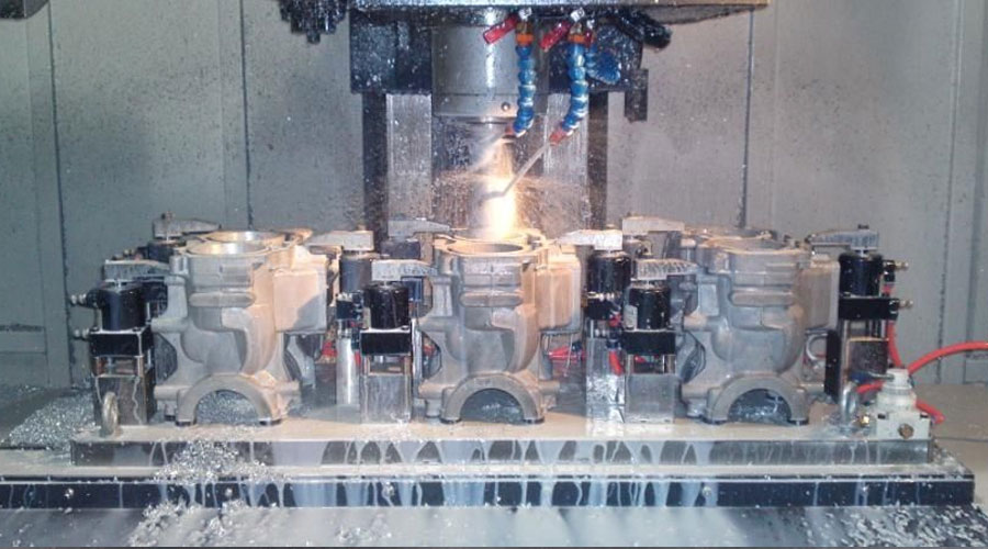
Workpiece installation
Positioning: Before machining, the workpiece must be placed on the machine table or fixture to make it occupy the correct position.
After the workpiece is positioned, it needs to be clamped in order to prevent it from deviating from the correct position due to the cutting force, gravity and inertial force during the cutting process.
Installation: the whole process from positioning to clamping of the workpiece.
When installing a workpiece, it is generally positioned first and then clamped. When installing a workpiece on a three-jaw chuck, positioning and clamping are performed simultaneously.
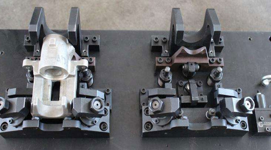
Installation method
(1) Direct mounting method
The workpiece is directly placed on the machine table or general fixture (such as standard accessories such as three-jaw chuck, four-jaw chuck, flat-nose pliers, electromagnetic chuck, etc.), and sometimes it is clamped without finding another correct, for example The three-jaw chuck or electromagnetic chuck is used to install the workpiece; sometimes it is necessary to align the workpiece according to a certain surface or scribe line on the workpiece, and then clamp it, such as installing the workpiece on the four-jaw chuck or on the machine table.
When installing workpieces in this way, it is time-consuming to find the alignment, and the positioning accuracy depends mainly on the accuracy of the tools or instruments used, and the technical level of the workers. The positioning accuracy is not easy to guarantee and the productivity is low, so it is usually only suitable for single parts Small batch production.
(2) Special fixture installation method
The fixture is specially designed and manufactured for the machining of a part. Without correcting, you can quickly and reliably ensure the correct relative position of the workpiece to the machine tool and the tool, and can quickly clamp.
The use of special fixtures to process workpieces can not only ensure the machining accuracy, but also improve the production efficiency, but there is no universality. The design, manufacture and maintenance of special fixtures require a certain investment, so only in batch production or mass production can relatively good results be achieved.
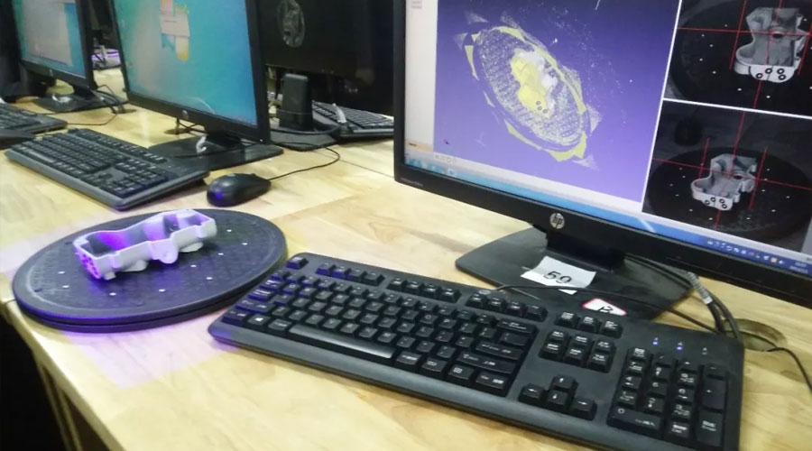
Classification and composition of machine tool fixtures
The jig and fixture for machine tool can be divided into general fixtures, special fixtures, combination fixtures, general adjustable fixtures and group fixtures according to their scope of use.
According to the machine tool used, the fixtures can be divided into lathe fixtures, milling machine fixtures, drilling machine fixtures (drill dies), boring machine fixtures (boring dies), grinder fixtures and gear machine fixtures.
According to the power source that generates the clamping force, the fixture can be divided into manual fixture, pneumatic fixture, hydraulic fixture, electric fixture, electromagnetic fixture and vacuum fixture.
The special fixture is generally composed of the following parts:
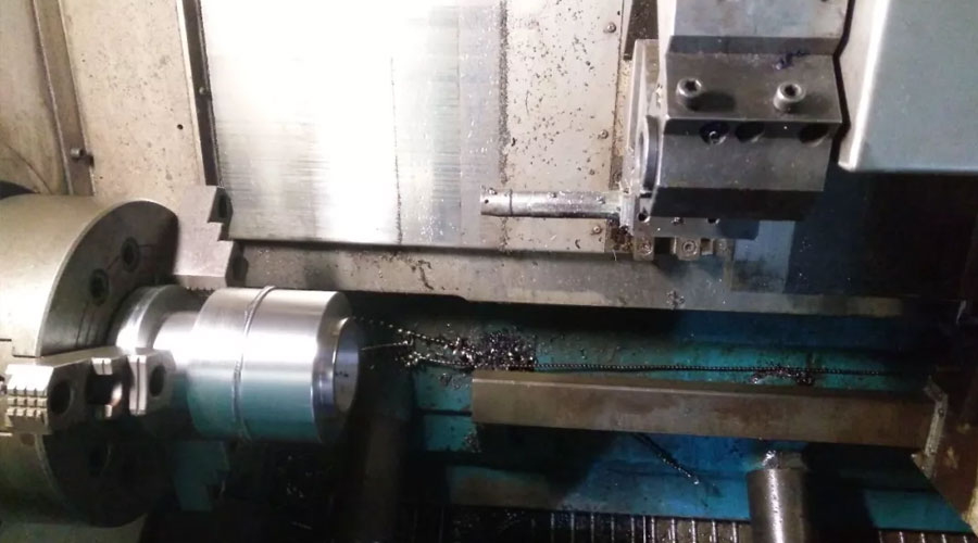
(1) Positioning element
The fixture is in contact with the selected positioning reference surface of the workpiece to determine the correct position of the workpiece.
When the workpiece is positioned in a plane, use the supporting nail and the supporting plate as positioning elements
When positioning the workpiece outside the cylindrical surface, the V-shaped block and positioning sleeve are used as fixed components
When the workpiece is positioned with a hole, the positioning mandrel and positioning pin are used as positioning elements.
(2) Clamping mechanism
A mechanism that clamps and tightens the workpiece after positioning to prevent the workpiece from displacement due to cutting forces and other external forces.
Commonly used clamping mechanisms include screw pressing plates, eccentric pressing plates, inclined wedge clamping mechanisms, hinge clamping mechanisms, etc.
(3) Guide element
The part used to set the tool and guide the tool into the correct machining position
Drill sleeves and guide sleeves are mainly used in drilling machine fixtures and boring machine fixtures, and tool setting blocks are mainly used in milling machine fixtures.
(4) Clamping parts and other parts
Clamping parts are the reference parts of the fixture. Use it to connect and fix the positioning element, clamping mechanism and guide element, etc., to make it a whole, and install the fixture on the machine tool.
According to the requirements of machining workpieces, sometimes there are indexing mechanism, guide keys, balance iron and operating parts on the fixture.
The entire fixture and its parts must have sufficient precision and rigidity, and the structure should be compact, the shape should be simple, and the work piece should be loaded and unloaded and the chip removal should be convenient.
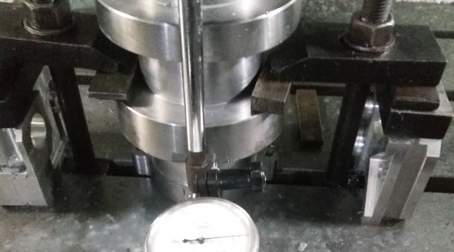
Benchmarks and selection
In the design and machining of parts, certain points, lines, and areas are often used to determine the geometric relationship between the elements. These points, lines, and areas are called datums.
Benchmark: Divided into two categories: design benchmark and process benchmark.
(1) Design basis
Design basis is the basis used on part drawings during design.
Based on the design basis to determine the size and mutual positional relationship between geometric elements
(2) Process benchmark
Process benchmark is the benchmark used in the process of manufacturing parts and assembling machines. Process benchmarks are divided into positioning benchmarks, measuring benchmarks and assembly benchmarks, which are used for positioning, measurement and inspection of workpieces and assembly of parts during workpiece machining.
Positioning reference: the surface of the workpiece to determine the relative position of the workpiece to the machine tool and tool during machining.
Rough reference: The positioning reference used in the initial process is the unmachined surface on the blank.
Fine datum: The positioning datum used in the subsequent processes is the machined surface.
(3) Rough reference
The selection of the rough reference should ensure that all the machined surfaces have sufficient machining allowance, and each machined surface has a certain position accuracy to the unmachined surface.
The specific principles of its selection are as follows:
- 1) Select the unmachined surface as the rough reference. If there are several unmachined surfaces on the part, you should select the surface that requires high mutual position accuracy with the machined surface as the rough reference.
- 2) Select a surface that requires a uniform machining allowance as a rough reference, so as to ensure that the surface used as a rough reference is uniform in machining.
- 3) For the parts to be machined on all surfaces, the surface with the smallest margin and tolerance should be selected as the rough reference to avoid the waste caused by insufficient margin.
- 4) In order to make the workpiece positioning stable and reliable clamping, it is required that the selected rough reference is as smooth and smooth as possible, no forging flash, casting gate riser cuts or other defects are allowed, and there is sufficient support area.
- 5) In the same size direction, the coarse reference is usually allowed to be used only once. This is because the coarse reference is generally very rough. If the same coarse reference is used repeatedly, the position error between the two sets of machined surfaces will be quite large. Therefore, the coarse reference Generally, it cannot be reused.
Fine reference The selection of fine reference should ensure the machining accuracy and reliable and convenient clamping.
The specific principles of its selection are as follows:
- 1) As much as possible, choose a surface with a larger size as a precision reference to improve the stability and accuracy of the installation.
- 2) The principle of benchmark coincidence, as far as possible, choose the design benchmark as the positioning benchmark, ie. This can avoid positioning errors caused by misalignment of the positioning reference and the design reference.
- 3) The unified principle of benchmarking. For some precise surfaces on parts, the mutual position accuracy often has high requirements. When finishing these surfaces, the same positioning reference should be selected as much as possible to help ensure the mutual position accuracy between the surfaces.
- 4) The principle of mutual reference. When the position accuracy between the two machined surfaces on the workpiece is relatively high, the method of repeatedly machining the two machined surfaces as a reference to each other can be used.
- 5) Self-based principle. When some surface finishing processes require a small and uniform margin (such as rail grinding), the surface to be machined can be used as a positioning reference, which is called the principle of self-reference. The position accuracy at this time should be guaranteed by the preceding process.
Link to this article: Workpiece installation and its fixtures
Reprint Statement: If there are no special instructions, all articles on this site are original. Please indicate the source for reprinting:https://www.cncmachiningptj.com/,thanks!
 PTJ® provides a full range of Custom Precision cnc machining china services.ISO 9001:2015 &AS-9100 certified. 3, 4 and 5-axis rapid precision CNC machining services including milling, turning to customer specifications,Capable of metal & plastic machined parts with +/-0.005 mm tolerance.Secondary services include CNC and conventional grinding, drilling,die casting,sheet metal and stamping.Providing prototypes, full production runs, technical support and full inspection.Serves the automotive, aerospace, mold&fixture,led lighting,medical,bicycle, and consumer electronics industries. On-time delivery.Tell us a little about your project’s budget and expected delivery time. We will strategize with you to provide the most cost-effective services to help you reach your target,Welcome to Contact us ( sales@pintejin.com ) directly for your new project.
- 5 Axis Machining
- Cnc Milling
- Cnc Turning
- Machining Industries
- Machining Process
- Surface Treatment
- Metal Machining
- Plastic Machining
- Powder Metallurgy Mold
- Die Casting
- Parts Gallery
- Auto Metal Parts
- Machinery Parts
- LED Heatsink
- Building Parts
- Mobile Parts
- Medical Parts
- Electronic Parts
- Tailored Machining
- Bicycle Parts
- Aluminum Machining
- Titanium Machining
- Stainless Steel Machining
- Copper Machining
- Brass Machining
- Super Alloy Machining
- Peek Machining
- UHMW Machining
- Unilate Machining
- PA6 Machining
- PPS Machining
- Teflon Machining
- Inconel Machining
- Tool Steel Machining
- More Material

