Design and CNC Machining of Plastic Shell Injection Molds Using Unigraphics and Moldflow
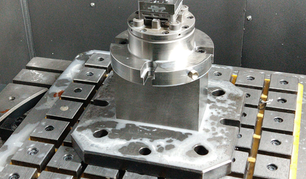
The design and manufacturing of plastic shell injection molds represent a cornerstone of modern industrial production, enabling the mass production of precise, high-quality plastic components used across industries such as automotive, electronics, medical devices, and consumer goods. The integration of advanced computer-aided design (CAD) and computer-aided engineering (CAE) tools, such as Unigraphics (UG, now known as Siemens NX) and Moldflow, has revolutionized the mold-making process by enhancing precision, reducing development time, and optimizing mold performance. Coupled with computer numerical control (CNC) machining, these tools facilitate the creation of complex mold geometries with tight tolerances, ensuring functionality and durability. This article provides an in-depth exploration of the processes, methodologies, and technologies involved in designing and machining plastic shell injection molds using UG and Moldflow, covering theoretical foundations, practical applications, and technical considerations.
Historical Context of Injection Molding and CAD/CAE Integration
Injection molding, developed in the late 19th century, became a dominant manufacturing process by the mid-20th century due to its ability to produce intricate plastic parts at scale. Early mold design relied heavily on manual drafting and empirical knowledge, often leading to prolonged development cycles and costly trial-and-error iterations. The advent of CAD systems in the 1960s, followed by CAE tools in the 1980s, marked a paradigm shift. Unigraphics, introduced by United Computing in 1973 and later acquired by Siemens, emerged as a powerful CAD/CAM platform, enabling designers to create detailed 3D models of molds. Moldflow, founded in 1978, pioneered plastic flow simulation, allowing engineers to predict and optimize the behavior of molten plastic during injection.
The synergy of UG and Moldflow has since become a standard in mold design, combining robust geometric modeling with sophisticated flow analysis. CNC machining, which gained prominence in the 1950s with numerical control systems, further complemented these tools by translating digital designs into physical molds with unprecedented accuracy. Today, the integration of these technologies ensures that plastic shell molds—used for thin-walled components like phone casings, laptop housings, and medical device enclosures—are produced efficiently and reliably.
Fundamentals of Plastic Shell Injection Molds
Definition and Characteristics
A plastic shell injection mold is a precision tool designed to shape molten plastic into thin-walled, hollow, or semi-hollow components. These molds typically consist of two primary halves: the cavity (forming the outer surface) and the core (forming the inner surface). Additional features, such as runners, gates, ejector pins, and cooling channels, are incorporated to facilitate the molding process. Plastic shells are characterized by their lightweight construction, high strength-to-weight ratio, and complex geometries, making them ideal for applications requiring aesthetic appeal and structural integrity.
Key Design Considerations
Designing a plastic shell mold involves balancing multiple factors, including part geometry, material selection, mold durability, and production efficiency. Thin walls (typically 0.5–2 mm) demand precise control over flow, pressure, and cooling to prevent defects like warpage, sink marks, or incomplete filling. The mold must also accommodate features like ribs, bosses, and snap-fits, which enhance functionality but complicate design and machining. Material selection—commonly thermoplastics like ABS, polycarbonate, or polypropylene—impacts flow behavior and mold design, necessitating compatibility with the chosen resin.
Role of UG and Moldflow
Unigraphics provides a comprehensive environment for creating and refining mold designs, offering tools for parametric modeling, surface design, and assembly management. Its CAM module generates toolpaths for CNC machining, ensuring seamless translation from design to production. Moldflow, conversely, simulates the injection molding process, analyzing parameters like fill time, pressure distribution, and cooling efficiency. Together, they enable iterative optimization, allowing designers to refine molds virtually before machining begins.
Unigraphics (Siemens NX) in Mold Design
Overview of Siemens NX
Siemens NX, formerly Unigraphics, is a versatile CAD/CAM/CAE platform used across industries for product design and manufacturing. Its mold design module is tailored for injection molds, offering specialized tools for cavity-core creation, parting surface definition, and mold base configuration. NX’s parametric modeling allows designers to modify geometries dynamically, while its hybrid modeling capabilities support both solid and surface-based designs, critical for complex shell geometries.
Mold Design Workflow in NX
The mold design process in NX begins with importing or creating a 3D model of the plastic shell. Designers define the parting line, which separates the cavity and core, using NX’s surface analysis tools to ensure moldability. The software automatically generates parting surfaces, accounting for draft angles (typically 1–3°) to facilitate part ejection. NX’s mold wizard streamlines the creation of standard components like ejector pins, sprues, and runners, drawing from libraries of mold bases (e.g., DME, Hasco).
Shrinkage compensation is a critical step, as plastics contract upon cooling (e.g., ABS shrinks ~0.4–0.7%). NX applies scaling factors to the part geometry, ensuring the mold produces parts to specification. Cooling channel design is another focal point, with NX enabling the placement of conformal or traditional channels to optimize heat transfer. The software’s assembly environment ensures all components align precisely, minimizing machining errors.
Advanced Features
NX’s synchronous technology allows non-parametric edits, enabling rapid adjustments to imported models without rebuilding constraints. Its mold flow analysis integration, though less comprehensive than Moldflow, provides preliminary simulations to validate gate locations and fill patterns. For complex shells, NX’s freeform modeling tools create smooth, aesthetic surfaces, while its validation tools check for undercuts, thin walls, or sharp corners that could hinder molding.
Comparison of NX with Other CAD Platforms
| Feature | Siemens NX | SolidWorks | CATIA | Creo Parametric |
|---|---|---|---|---|
| Parametric Modeling | Advanced, with synchronous edits | Strong, user-friendly | Robust, aerospace-focused | Strong, mechanism-driven |
| Mold Design Tools | Comprehensive mold wizard | Dedicated mold tools | Advanced surface modeling | Mold-specific modules |
| Surface Modeling | Hybrid solid/surface | Moderate surface capabilities | Industry-leading surfaces | Good, but less intuitive |
| CAM Integration | Seamless NX CAM | Integrated, but less advanced | Strong, with DELMIA | Integrated, robust |
| Simulation Capabilities | Basic flow analysis | Limited, via Plastics add-on | Extensive, with SIMULIA | Moderate, with Creo Simulate |
| Learning Curve | Moderate to steep | Easy to moderate | Steep | Moderate |
| Cost | High | Moderate | Very high | High |
This table highlights NX’s strengths in mold design, particularly its CAM integration and mold wizard, though its cost and learning curve may deter smaller firms.
Moldflow Analysis for Plastic Shell Molds
Introduction to Moldflow
Moldflow, developed by Autodesk, is a leading CAE tool for simulating injection molding processes. It predicts how molten plastic behaves within the mold, identifying potential defects and optimizing design parameters. For plastic shells, Moldflow’s ability to analyze thin-wall filling, cooling, and warpage is invaluable, ensuring molds produce high-quality parts with minimal iterations.
Moldflow Workflow
The Moldflow process begins with importing the mold or part geometry, typically from NX, in formats like STEP or IGES. Users define material properties, selecting from Moldflow’s extensive database of over 11,000 polymers (e.g., PC/ABS blends for shells). Gate locations are specified, often iteratively, to balance fill patterns. The simulation then models the filling, packing, cooling, and warpage phases, generating data on pressure, temperature, and deformation.
Filling Analysis
Filling analysis predicts how plastic flows into the cavity, identifying issues like short shots (incomplete filling) or weld lines (where flow fronts meet, potentially weakening the part). For shells, uniform filling is critical to avoid uneven shrinkage. Moldflow’s color-coded fill time maps highlight areas of delayed filling, guiding gate repositioning or wall thickness adjustments.
Packing Analysis
Packing compensates for shrinkage by applying pressure post-filling. Moldflow optimizes packing pressure and time, reducing sink marks—common in thick-to-thin transitions on shells. Excessive packing, however, can cause residual stresses, which Moldflow quantifies to balance part quality and cycle time.
Cooling Analysis
Cooling accounts for ~80% of the molding cycle, making it a focal point for shells requiring fast production. Moldflow simulates heat transfer through cooling channels, predicting temperature distributions and cycle times. Conformal cooling, where channels follow the part’s contours, is often analyzed to enhance efficiency, particularly for complex shells.
Warpage Analysis
Warpage, a prevalent defect in thin-walled parts, results from uneven cooling or material orientation. Moldflow’s warpage analysis predicts deformations (e.g., 0.5–2 mm for a 100 mm shell) and suggests remedies like adjusting cooling layouts or gate positions. For fiber-reinforced plastics, it also models fiber orientation, which impacts strength and warpage.
Moldflow Outputs and Interpretation
Moldflow generates detailed reports, including:
- Fill Time: Time to fill the cavity (e.g., 1–3 seconds for shells).
- Pressure at V/P Switchover: Pressure when switching from filling to packing (~50–100 MPa).
- Cooling Time: Time to reach ejection temperature (~10–30 seconds).
- Warpage: Displacement maps showing deformation patterns.
These outputs inform design iterations, such as increasing wall thickness from 1 mm to 1.2 mm to reduce warpage or relocating gates to minimize weld lines.
Comparison of Moldflow with Other CAE Tools
| Feature | Autodesk Moldflow | Moldex3D | SolidWorks Plastics | Sigmasoft |
|---|---|---|---|---|
| Material Database | Extensive (~11,000 polymers) | Large (~8,000 polymers) | Moderate (~5,000 polymers) | Large (~7,000 polymers) |
| Filling Analysis | Highly accurate | Very accurate | Good, but less detailed | Accurate, process-focused |
| Cooling Analysis | Advanced, conformal support | Strong, with mold movement | Basic, limited conformal | Advanced, multi-cycle |
| Warpage Prediction | Precise, fiber orientation | Excellent, with anisotropy | Moderate, simplified | Strong, material-specific |
| User Interface | Moderate learning curve | Intuitive, modern | User-friendly, CAD-integrated | Complex, engineering-focused |
| Integration with CAD | Good (STEP, IGES) | Excellent (direct NX link) | Seamless with SolidWorks | Moderate, file-based |
| Cost | High | High | Moderate | Very high |
Moldflow excels in material variety and warpage analysis, making it ideal for plastic shells, though Moldex3D offers superior CAD integration.
CNC Machining of Plastic Shell Molds
Overview of CNC Machining
CNC machining uses computer-controlled tools to remove material from a workpiece, shaping it into a precise component. For injection molds, CNC milling, turning, and electrical discharge machining (EDM) are common, with 3- to 5-axis machines enabling complex geometries. Steel (e.g., P20, H13) or aluminum is typically used, with steel preferred for high-volume shell molds due to its durability.
CNC Machining Workflow
The machining process begins with the mold design, finalized in NX. The CAM module generates toolpaths, specifying cutter types (e.g., end mills, ball mills), speeds, and feeds. For shells, high-speed milling ensures smooth cavity surfaces, critical for aesthetic parts. EDM is used for fine details like sharp corners or deep ribs, while turning shapes cylindrical components like cores or sprues.
Toolpath Generation
NX CAM optimizes toolpaths for efficiency and surface finish. Roughing removes bulk material with large cutters (e.g., 10 mm end mills), while finishing uses smaller tools (e.g., 2 mm ball mills) for precision. Adaptive clearing strategies minimize tool wear, extending cutter life by ~20–30%. For conformal cooling channels, 5-axis machining ensures accurate placement, reducing cycle times by up to 40%.
Material Considerations
Steel molds require slower cutting speeds (e.g., 100–200 m/min for P20) but offer longevity (1–5 million cycles). Aluminum, machined faster (e.g., 300–500 m/min), suits prototypes or low-volume runs (<100,000 cycles) but wears faster. NX’s material libraries adjust parameters automatically, ensuring compatibility.
Post-Machining Processes
After CNC machining, molds undergo polishing to achieve surface finishes (e.g., SPI A-1 for glossy shells), heat treatment to enhance hardness (e.g., 48–52 HRC for H13), and assembly. NX’s inspection tools verify dimensions against the CAD model, ensuring tolerances of ±0.01 mm.
Challenges in CNC Machining Shell Molds
Thin-walled geometries require precise tool control to avoid chatter, which can degrade surface quality. Deep cavities increase tool deflection risks, necessitating rigid setups or shorter tools. Cooling channel machining demands high accuracy, as misalignments can reduce cooling efficiency by 10–20%. NX’s simulation tools mitigate these issues by predicting tool behavior and suggesting adjustments.
Comparison of CNC Machining Techniques
| Technique | Milling | Turning | EDM | Wire EDM |
|---|---|---|---|---|
| Application | Cavities, cores, channels | Cylindrical components | Fine details, sharp corners | Precision cuts, slots |
| Material Removal Rate | High (10–50 cm³/min) | Moderate (5–20 cm³/min) | Low (0.1–1 cm³/min) | Very low (0.05–0.5 cm³/min) |
| Surface Finish | Good (Ra 0.4–1.6 µm) | Excellent (Ra 0.2–0.8 µm) | Excellent (Ra 0.1–0.4 µm) | Superior (Ra 0.05–0.2 µm) |
| Tolerance | ±0.01–0.05 mm | ±0.005–0.02 mm | ±0.002–0.01 mm | ±0.001–0.005 mm |
| Complexity Handling | High, 3–5 axis | Limited to rotation | High, electrode-based | Moderate, 2D profiles |
| Cost | Moderate | Low | High | Very high |
Milling dominates shell mold machining due to its versatility, with EDM supplementing for intricate features.
Integration of UG, Moldflow, and CNC Machining
Iterative Design Process
The mold design process is inherently iterative, with UG and Moldflow facilitating rapid cycles of design, analysis, and refinement. A typical workflow involves:
- Part Design in NX: Create the shell geometry, incorporating draft angles and fillets.
- Moldflow Analysis: Simulate filling, packing, and cooling, adjusting gates or channels as needed.
- Mold Design in NX: Finalize cavity, core, and auxiliaries, applying shrinkage factors.
- Moldflow Validation: Re-run simulations to confirm performance.
- CNC Toolpath Generation: Use NX CAM to program machining operations.
- Machining and Assembly: Fabricate and assemble the mold.
- Testing and Iteration: Mold trials identify issues, feeding back into NX/Moldflow for refinements.
This cycle reduces development time by 30–50% compared to traditional methods, as virtual optimization minimizes physical trials.
Data Exchange and Compatibility
NX and Moldflow integrate seamlessly via neutral formats (STEP, IGES) or direct connectors, ensuring accurate geometry transfer. Moldflow’s results (e.g., warpage data) can be imported into NX to adjust designs, while NX’s toolpaths leverage Moldflow’s material data for precise machining. Challenges include mesh compatibility—NX’s solid models require conversion to Moldflow’s finite element meshes, which can introduce errors if not managed carefully.
Case Study: Smartphone Shell Mold
Consider a polycarbonate smartphone shell (120 × 60 × 1 mm). In NX, the part is designed with a 1.5° draft and 0.5 mm fillets. Moldflow simulates filling with a single gate, revealing a weld line near the camera cutout. Repositioning the gate to the shell’s edge balances flow, reducing warpage from 1.2 mm to 0.4 mm. NX designs a P20 steel mold with conformal cooling channels, machined via 5-axis milling. The mold produces 500,000 parts with ±0.05 mm tolerances, demonstrating the power of integrated tools.
Practical Considerations and Best Practices
Design Guidelines
- Wall Thickness: Maintain uniformity (e.g., 1–1.5 mm) to prevent sink marks.
- Draft Angles: Apply 1–3° for easy ejection, adjusting for textured surfaces.
- Gate Selection: Use fan or edge gates for shells to ensure even flow.
- Cooling Layout: Place channels 5–10 mm from surfaces, optimizing for cycle time.
Machining Tips
- Tool Selection: Use carbide tools for steel, coated for aluminum to extend life.
- Speeds and Feeds: Balance speed (e.g., 10,000–20,000 RPM) with feed rates (0.05–0.2 mm/tooth) for finish quality.
- Setup Rigidity: Minimize vibration with robust fixtures, especially for deep cavities.
Simulation Strategies
- Mesh Quality: Use fine meshes (~0.5 mm elements) near gates and coarse elsewhere to balance accuracy and computation time.
- Material Data: Verify polymer properties (e.g., viscosity, shrinkage) against supplier specs.
- Iterative Analysis: Run multiple simulations with varying gate locations or pressures to identify optimal settings.
Industry Applications
Plastic shell molds are ubiquitous in:
- Electronics: Housings for smartphones, laptops, and wearables.
- Automotive: Interior panels, light covers, and dashboard components.
- Medical: Disposable device casings, syringe barrels.
- Consumer Goods: Packaging, appliance covers, and toys.
Each sector demands specific tolerances and finishes, with electronics requiring high aesthetics (SPI A-1) and medical prioritizing biocompatibility.
Challenges and Future Trends
Current Challenges
- Complexity: Shells with intricate features (e.g., multi-material overmolding) strain design and machining capabilities.
- Cost: High-end molds cost $50,000–$500,000, necessitating ROI justification.
- Lead Time: Despite advancements, mold development can take 8–16 weeks, challenging rapid prototyping needs.
Emerging Technologies
- Additive Manufacturing: 3D-printed mold inserts reduce lead times for prototypes, though durability lags.
- AI Optimization: Machine learning enhances Moldflow predictions, suggesting gate placements or cooling layouts.
- Sustainable Materials: Bio-based plastics require new simulation models, expanding Moldflow’s database.
- Digital Twins: Real-time mold monitoring integrates with NX/Moldflow, predicting maintenance needs.
Conclusion
The design and CNC machining of plastic shell injection molds using Unigraphics and Moldflow exemplify the convergence of creativity and precision in modern manufacturing. Siemens NX’s robust CAD/CAM tools enable intricate mold designs, while Moldflow’s simulations ensure process reliability. CNC machining translates these designs into durable, high-performance molds, meeting the demands of diverse industries. As technology evolves, integrating AI, additive manufacturing, and sustainable practices will further enhance efficiency and innovation, solidifying the role of these tools in shaping the future of injection molding.
Reprint Statement: If there are no special instructions, all articles on this site are original. Please indicate the source for reprinting:https://www.cncmachiningptj.com/,thanks!
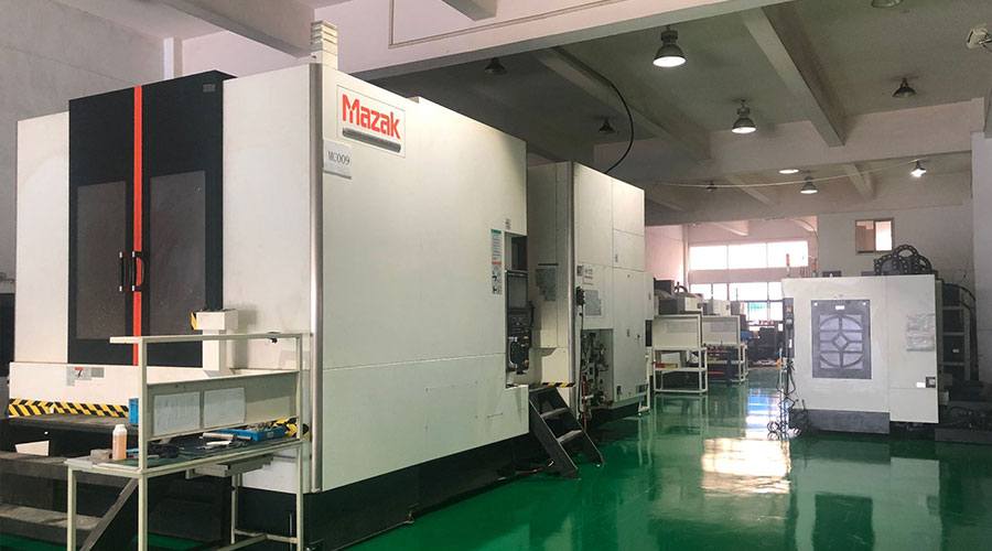 3, 4 and 5-axis precision CNC machining services for aluminum machining, beryllium, carbon steel, magnesium, titanium machining, Inconel, platinum, superalloy, acetal, polycarbonate, fiberglass, graphite and wood. Capable of machining parts up to 98 in. turning dia. and +/-0.001 in. straightness tolerance. Processes include milling, turning, drilling, boring, threading, tapping, forming, knurling, counterboring, countersinking, reaming and laser cutting. Secondary services such as assembly, centerless grinding, heat treating, plating and welding. Prototype and low to high volume production offered with maximum 50,000 units. Suitable for fluid power, pneumatics, hydraulics and valve applications. Serves the aerospace, aircraft, military, medical and defense industries.PTJ will strategize with you to provide the most cost-effective services to help you reach your target,Welcome to Contact us ( sales@pintejin.com ) directly for your new project.
- 5 Axis Machining
- Cnc Milling
- Cnc Turning
- Machining Industries
- Machining Process
- Surface Treatment
- Metal Machining
- Plastic Machining
- Powder Metallurgy Mold
- Die Casting
- Parts Gallery
- Auto Metal Parts
- Machinery Parts
- LED Heatsink
- Building Parts
- Mobile Parts
- Medical Parts
- Electronic Parts
- Tailored Machining
- Bicycle Parts
- Aluminum Machining
- Titanium Machining
- Stainless Steel Machining
- Copper Machining
- Brass Machining
- Super Alloy Machining
- Peek Machining
- UHMW Machining
- Unilate Machining
- PA6 Machining
- PPS Machining
- Teflon Machining
- Inconel Machining
- Tool Steel Machining
- More Material

