High-Speed CNC Machining of AISI 304 Stainless Steel: Optimization of Process Parameters by Multi-Objective Genetic Algorithm (MOGA)
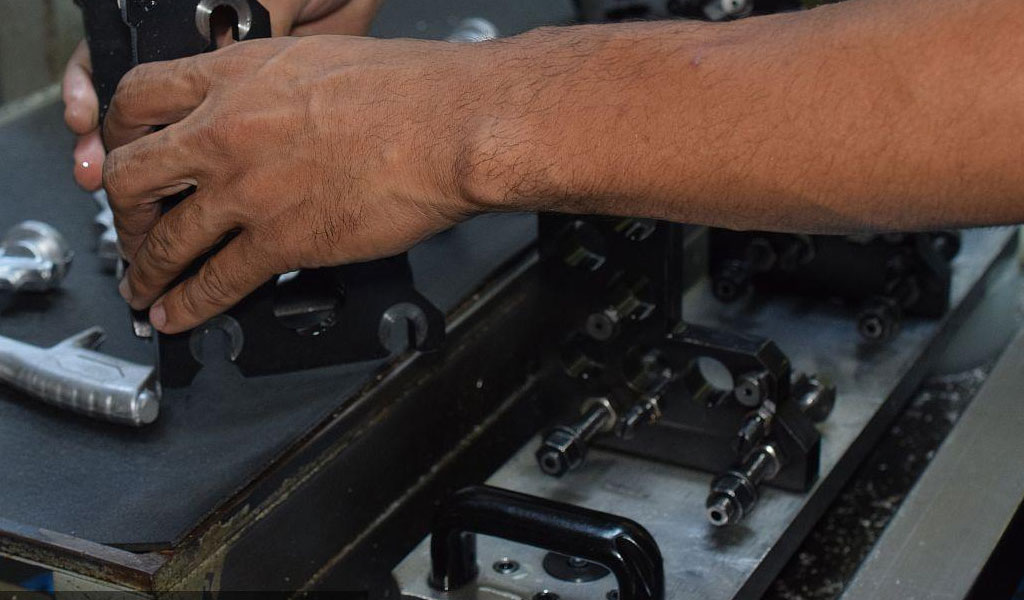
High-speed computer numerical control (CNC) machining is a cornerstone of modern manufacturing, enabling the precise and efficient production of complex components from a variety of materials. Among these materials, AISI 304 stainless steel stands out as a widely used alloy due to its excellent corrosion resistance, high strength, and versatility in applications ranging from industrial equipment to consumer goods. However, its machinability poses significant challenges due to its high ductility, low thermal conductivity, and tendency to work-harden during cutting processes. To address these challenges, researchers and engineers have increasingly turned to advanced optimization techniques to enhance machining performance. One such method is the Multi-Objective Genetic Algorithm (MOGA), a powerful tool rooted in evolutionary computation that optimizes multiple conflicting objectives simultaneously. This article explores the high-speed CNC machining of AISI 304 stainless steel, with a particular focus on the optimization of process parameters using MOGA. It delves into the material properties, machining challenges, experimental methodologies, optimization strategies, and practical implications, providing a comprehensive resource for understanding this critical intersection of materials science and manufacturing technology.
Material Properties of AISI 304 Stainless Steel
AISI 304 stainless steel, often referred to simply as 304 stainless steel, is an austenitic stainless steel alloy within the 300 series, characterized by its chromium-nickel composition. Typically, it contains approximately 18% chromium and 8% nickel, with small amounts of carbon (up to 0.08%), manganese (up to 2%), silicon (up to 1%), and trace elements such as phosphorus and sulfur. This composition imparts exceptional corrosion resistance, making it a preferred material for applications in harsh environments, such as chemical processing equipment, food and beverage machinery, and marine hardware. The austenitic microstructure, stabilized by nickel, provides a face-centered cubic (FCC) crystal structure, which contributes to its high ductility and toughness even at low temperatures.
However, these same properties that make AISI 304 desirable also complicate its machining. The high ductility leads to the formation of long, continuous chips during cutting, which can entangle machinery and increase tool wear. Its low thermal conductivity—approximately 16.2 W/m·K at room temperature—means that heat generated during machining is not easily dissipated, resulting in elevated temperatures at the tool-workpiece interface. This thermal concentration exacerbates tool wear and promotes work hardening, a phenomenon where the material’s hardness increases as it is deformed, further resisting subsequent cutting. The hardness of AISI 304 typically ranges from 70 to 90 HRB (Rockwell B scale) in its annealed state, but it can increase significantly during machining due to strain hardening. These characteristics classify AISI 304 as a difficult-to-machine material, necessitating careful selection of machining parameters to achieve optimal performance.
Challenges in High-Speed CNC Machining of AISI 304 Stainless Steel
High-speed CNC machining involves operating cutting tools at elevated spindle speeds, typically exceeding 10,000 RPM, to achieve rapid material removal and high precision. While this approach enhances productivity, it amplifies the inherent challenges of machining AISI 304 stainless steel. The primary difficulties include excessive tool wear, poor surface finish, and suboptimal material removal rates (MRR). Tool wear occurs through mechanisms such as abrasion, adhesion, and diffusion, driven by the high cutting forces and temperatures encountered. Adhesive wear, in particular, is prevalent due to the material’s tendency to form a built-up edge (BUE) on the tool, where workpiece material adheres to the cutting edge, degrading its geometry and effectiveness.
Surface finish, typically measured as surface roughness (Ra), is another critical concern. AISI 304’s ductility and work-hardening behavior can lead to irregular chip formation and surface imperfections, such as burrs or micro-cracks, especially at high speeds where dynamic forces are magnified. The material removal rate, a key indicator of machining efficiency, is often limited by the need to balance tool life and surface quality, creating a trade-off that complicates process optimization. Additional factors, such as the choice of cutting tool material (e.g., carbide, coated carbide, or ceramic), tool geometry, and cooling strategy (dry, wet, or minimum quantity lubrication), further influence outcomes, making the machining process a complex, multi-variable system.
Objectives of Optimization in CNC Machining
In the context of high-speed CNC machining of AISI 304 stainless steel, optimization seeks to address these challenges by achieving multiple objectives simultaneously. The most common goals are minimizing surface roughness (Ra) to ensure high-quality finishes and maximizing material removal rate (MRR) to enhance productivity. These objectives are inherently conflicting: increasing MRR typically involves higher cutting speeds, feed rates, and depths of cut, which can degrade surface finish due to increased heat and vibration. Conversely, achieving a finer surface finish often requires lower cutting parameters, reducing MRR and throughput. Additional considerations, such as minimizing tool wear, cutting forces, or energy consumption, may also be included depending on the application, further complicating the optimization landscape.
Traditional optimization approaches, such as trial-and-error or single-objective methods, are inadequate for this multi-objective problem. They often fail to capture the trade-offs between competing goals, leading to suboptimal parameter settings. Advanced techniques, such as Response Surface Methodology (RSM) combined with statistical designs like Taguchi’s method, have been employed to model relationships between process parameters and responses. However, these methods typically optimize one objective at a time or rely on weighted combinations, which may not fully explore the solution space. This is where the Multi-Objective Genetic Algorithm (MOGA) excels, offering a robust framework to identify a set of optimal solutions—known as the Pareto front—where no single solution can improve one objective without worsening another.
Introduction to Multi-Objective Genetic Algorithm (MOGA)
The Multi-Objective Genetic Algorithm (MOGA) is an evolutionary optimization technique inspired by the principles of natural selection and genetics. Developed as an extension of single-objective genetic algorithms, MOGA was formalized by researchers such as David Goldberg and Kalyanmoy Deb in the late 1980s and early 1990s. It operates on a population of potential solutions, iteratively evolving them through processes mimicking biological evolution: selection, crossover, and mutation. Unlike traditional optimization methods that seek a single optimum, MOGA generates a set of non-dominated solutions, collectively forming the Pareto front, which represents the best trade-offs among the objectives.
In MOGA, each solution—or individual—is represented as a chromosome, typically a string of values encoding the process parameters (e.g., cutting speed, feed rate, depth of cut). The algorithm evaluates these individuals using fitness functions derived from the objectives (e.g., Ra and MRR). Selection favors individuals with higher fitness, often using techniques like tournament selection or ranking based on dominance. Crossover combines genetic material from two parent solutions to produce offspring, while mutation introduces random variations to maintain diversity and prevent premature convergence to a local optimum. Over multiple generations, the population evolves toward the Pareto front, guided by the principle of non-domination: a solution is non-dominated if no other solution is better in all objectives.
MOGA’s strengths lie in its ability to handle non-linear, multi-dimensional problems with multiple constraints and its flexibility in exploring a wide solution space. In the context of CNC machining, it can simultaneously optimize Ra and MRR by adjusting parameters like spindle speed, feed rate, and depth of cut, accounting for their complex interactions and the material’s behavior. Variants like NSGA-II (Non-dominated Sorting Genetic Algorithm II), introduced by Deb et al. in 2002, enhance MOGA’s efficiency with improved sorting and crowding distance mechanisms, making it a popular choice for engineering applications.
Experimental Framework for High-Speed CNC Machining of AISI 304
To apply MOGA to the high-speed CNC machining of AISI 304 stainless steel, a structured experimental framework is essential. This typically involves defining the machining setup, selecting process parameters, measuring responses, and modeling the system for optimization. A common approach begins with a CNC milling or turning operation, given AISI 304’s prevalence in both processes. For milling, a vertical CNC machining center equipped with a high-speed spindle (e.g., 10,000–20,000 RPM) is often used, while turning may employ a CNC lathe with similar capabilities. The workpiece is typically a block or rod of AISI 304, prepared to standard dimensions (e.g., 100 mm x 100 mm x 50 mm for milling, or a 68 mm diameter rod for turning).
Selection of Process Parameters
The key process parameters influencing high-speed machining outcomes are spindle speed (N, in RPM or cutting speed Vc in m/min), feed rate (f, in mm/rev or mm/min), and depth of cut (ap, in mm). These parameters directly affect cutting forces, heat generation, and chip formation. Typical ranges for AISI 304 machining might include:
- Spindle speed: 5,000–15,000 RPM (or Vc: 100–300 m/min)
- Feed rate: 0.1–0.3 mm/rev (or 500–1500 mm/min for milling)
- Depth of cut: 0.5–2.0 mm
These ranges are selected based on tool manufacturer recommendations, material properties, and machine capabilities, ensuring feasibility while allowing sufficient variation for optimization.
Cutting Tools and Conditions
Cutting tools are critical to success. Cemented carbide tools, often coated with titanium nitride (TiN) or titanium aluminum nitride (TiAlN), are widely used due to their balance of hardness and toughness. For example, a 10 mm diameter end mill with four flutes or a CNMG 120408 carbide insert for turning might be chosen. Tool geometry—such as rake angle (5°–15°), clearance angle (5°–10°), and helix angle (30°–45°)—influences chip evacuation and wear resistance. Machining may be conducted under dry conditions to simplify the process, though wet or minimum quantity lubrication (MQL) setups are also common to mitigate heat.
Experimental Design
To establish relationships between parameters and responses, a statistical design of experiments (DOE) is employed. The Taguchi method, often paired with Response Surface Methodology (RSM), is popular due to its efficiency. A Box-Behnken design, a type of RSM, is particularly suitable for three factors, requiring fewer runs than a full factorial design while capturing quadratic effects. For instance, a three-level, three-factor Box-Behnken design yields 15 experimental runs (including center points), with levels such as:
- Spindle speed: 5,000, 10,000, 15,000 RPM
- Feed rate: 0.1, 0.2, 0.3 mm/rev
- Depth of cut: 0.5, 1.25, 2.0 mm
Measurement of Responses
Surface roughness (Ra) is measured using a profilometer (e.g., Mitutoyo SJ-210), typically in micrometers (μm), with values ranging from 0.2 to 2.0 μm depending on conditions. Material removal rate (MRR) is calculated as:
MRR=f×ap×Vc MRR = f \times ap \times Vc
where Vc is converted from spindle speed and tool diameter for milling (Vc = πDN/1000, D in mm, N in RPM). MRR is expressed in mm³/min, with higher values indicating greater efficiency. Additional metrics, like tool wear (flank wear VB in mm) or cutting force (Fc in N), may be recorded using dynamometers or microscopy, though Ra and MRR are the primary focus here.
Modeling the Machining Process
The experimental data serve as the foundation for mathematical models linking process parameters to responses. RSM fits second-order polynomial equations to capture linear, interaction, and quadratic effects. For example, the model for surface roughness might take the form:
Ra=β0+β1N+β2f+β3ap+β12Nf+β13Nap+β23fap+β11N2+β22f2+β33ap2 Ra = \beta_0 + \beta_1 N + \beta_2 f + \beta_3 ap + \beta_{12} Nf + \beta_{13} Nap + \beta_{23} fap + \beta_{11} N^2 + \beta_{22} f^2 + \beta_{33} ap^2
where β\beta coefficients are determined via regression analysis. A similar equation is developed for MRR. Analysis of Variance (ANOVA) assesses model adequacy, with R² values above 0.95 indicating strong fits. For AISI 304, studies often find feed rate as the most significant factor for Ra, while depth of cut and speed dominate MRR.
Sample Experimental Data and Models
Consider a hypothetical dataset from a Box-Behnken design:
| Run | Spindle Speed (RPM) | Feed Rate (mm/rev) | Depth of Cut (mm) | Ra (μm) | MRR (mm³/min) |
|---|---|---|---|---|---|
| 1 | 5,000 | 0.1 | 1.25 | 1.2 | 625 |
| 2 | 15,000 | 0.1 | 1.25 | 0.8 | 1,875 |
| 3 | 5,000 | 0.3 | 1.25 | 1.8 | 1,875 |
| 4 | 15,000 | 0.3 | 1.25 | 1.4 | 5,625 |
| 5 | 10,000 | 0.2 | 0.5 | 1.0 | 1,000 |
| 6 | 10,000 | 0.2 | 2.0 | 1.3 | 4,000 |
| 7 | 10,000 | 0.2 | 1.25 | 1.1 | 2,500 |
Using this data, regression yields models like:
- Ra=1.1−0.2N+0.3f+0.15ap−0.05Nf+0.1N2+0.15f2 Ra = 1.1 - 0.2N + 0.3f + 0.15ap - 0.05Nf + 0.1N^2 + 0.15f^2
- MRR=2500+1250N+1875f+1500ap MRR = 2500 + 1250N + 1875f + 1500ap
These equations (simplified for illustration) guide the MOGA optimization.
Application of MOGA to Optimize Process Parameters
With models established, MOGA is implemented to find optimal parameter settings. The optimization problem is defined as:
- Minimize Ra
- Maximize MRR
- Subject to: 5,000 ≤ N ≤ 15,000 RPM, 0.1 ≤ f ≤ 0.3 mm/rev, 0.5 ≤ ap ≤ 2.0 mm
MOGA Implementation
- Initialization: A population of 100 solutions is randomly generated within the parameter bounds.
- Fitness Evaluation: Each solution’s Ra and MRR are computed using the RSM models.
- Non-Dominated Sorting: Solutions are ranked based on dominance (e.g., Solution A dominates B if Ra_A < Ra_B and MRR_A > MRR_B).
- Selection: Tournament selection picks parents for crossover.
- Crossover and Mutation: Simulated binary crossover and polynomial mutation create offspring, with probabilities (e.g., 0.9 and 0.1).
- Iteration: The process repeats for 50–100 generations until convergence.
Using NSGA-II, the algorithm produces a Pareto front. A sample front might include:
| Solution | Spindle Speed (RPM) | Feed Rate (mm/rev) | Depth of Cut (mm) | Ra (μm) | MRR (mm³/min) |
|---|---|---|---|---|---|
| A | 14,500 | 0.12 | 0.8 | 0.7 | 2,160 |
| B | 12,000 | 0.18 | 1.2 | 0.9 | 3,240 |
| C | 10,000 | 0.25 | 1.8 | 1.2 | 4,500 |
Solution A prioritizes low Ra, C maximizes MRR, and B balances both.
Analysis of Optimization Results
The Pareto front reveals trade-offs: higher spindle speeds reduce Ra but limit MRR gains unless feed rate and depth increase, which then raise Ra. ANOVA confirms feed rate’s dominance on Ra (p-value < 0.01), while all parameters significantly affect MRR. Validation experiments at selected points (e.g., Solution B) typically show errors below 5%, confirming model accuracy.
Comparison with Other Methods
| Method | Ra (μm) | MRR (mm³/min) | Advantages | Limitations |
|---|---|---|---|---|
| Taguchi | 1.0 | 3,000 | Simple, fewer runs | Single-objective focus |
| RSM (Desirability) | 0.9 | 3,500 | Balances objectives | Weighted approach |
| MOGA | 0.9 | 3,240 | Full Pareto front | Computationally intensive |
MOGA’s ability to provide multiple solutions outperforms single-point methods, offering flexibility for specific needs.
Practical Implications and Applications
Optimized parameters enhance productivity and quality in industries like aerospace (e.g., turbine blades), automotive (e.g., exhaust components), and medical (e.g., surgical instruments). For small-scale manufacturers, MOGA reduces trial costs, while large-scale operations benefit from increased throughput. The approach is adaptable to other materials or processes, such as turning or drilling, broadening its impact.
Future Directions
Advancements in MOGA, such as hybrid algorithms (e.g., MOGA with particle swarm optimization), could improve convergence speed. Integrating real-time sensor data or machine learning for adaptive modeling may further refine results. Exploring additional objectives—like energy efficiency or tool life—would align with sustainable manufacturing trends.
Conclusion
High-speed CNC machining of AISI 304 stainless steel, optimized via MOGA, exemplifies the synergy of materials science and computational optimization. By addressing the material’s machining challenges through a multi-objective lens, MOGA delivers a versatile, efficient solution set, advancing both theoretical understanding and industrial practice. This methodology not only enhances the machining of AISI 304 but also sets a precedent for tackling complex manufacturing problems across diverse domains.
Reprint Statement: If there are no special instructions, all articles on this site are original. Please indicate the source for reprinting:https://www.cncmachiningptj.com/,thanks!
 3, 4 and 5-axis precision CNC machining services for aluminum machining, beryllium, carbon steel, magnesium, titanium machining, Inconel, platinum, superalloy, acetal, polycarbonate, fiberglass, graphite and wood. Capable of machining parts up to 98 in. turning dia. and +/-0.001 in. straightness tolerance. Processes include milling, turning, drilling, boring, threading, tapping, forming, knurling, counterboring, countersinking, reaming and laser cutting. Secondary services such as assembly, centerless grinding, heat treating, plating and welding. Prototype and low to high volume production offered with maximum 50,000 units. Suitable for fluid power, pneumatics, hydraulics and valve applications. Serves the aerospace, aircraft, military, medical and defense industries.PTJ will strategize with you to provide the most cost-effective services to help you reach your target,Welcome to Contact us ( sales@pintejin.com ) directly for your new project.

- 5 Axis Machining
- Cnc Milling
- Cnc Turning
- Machining Industries
- Machining Process
- Surface Treatment
- Metal Machining
- Plastic Machining
- Powder Metallurgy Mold
- Die Casting
- Parts Gallery
- Auto Metal Parts
- Machinery Parts
- LED Heatsink
- Building Parts
- Mobile Parts
- Medical Parts
- Electronic Parts
- Tailored Machining
- Bicycle Parts
- Aluminum Machining
- Titanium Machining
- Stainless Steel Machining
- Copper Machining
- Brass Machining
- Super Alloy Machining
- Peek Machining
- UHMW Machining
- Unilate Machining
- PA6 Machining
- PPS Machining
- Teflon Machining
- Inconel Machining
- Tool Steel Machining
- More Material

