A Review of Machine-Tool Vibration and Its Influence upon Surface Generation in Ultra-Precision Machining
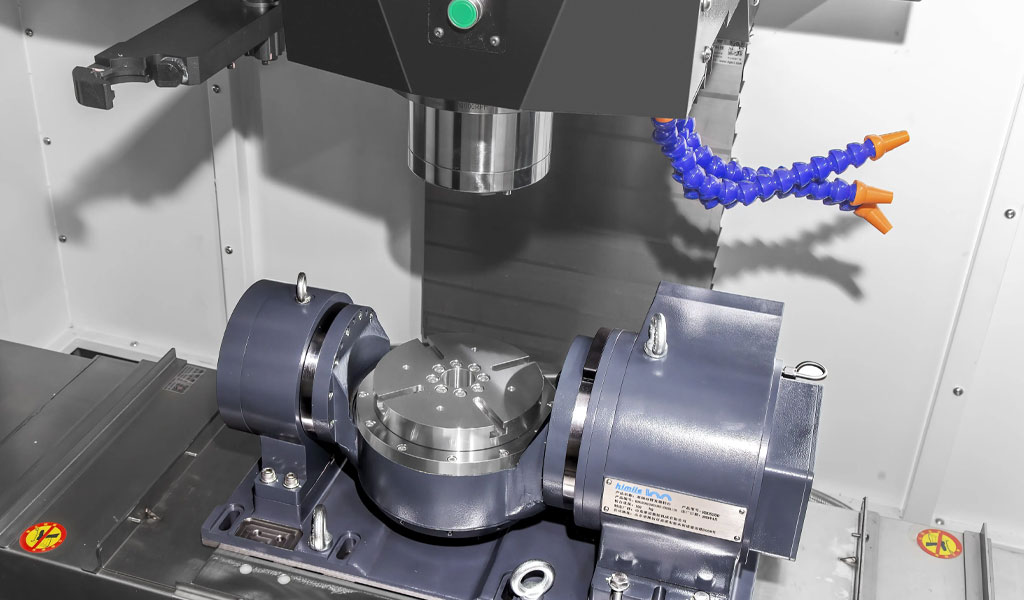
Ultra-precision machining (UPM) represents a pinnacle of manufacturing technology, enabling the production of components with nanometric surface roughness and sub-micrometric form accuracy. This level of precision is critical for applications in optics, aerospace, biomedical devices, and microelectronics, where surface quality directly impacts functional performance. However, achieving such exacting standards is challenged by numerous factors, among which machine-tool vibration stands out as a pervasive and influential phenomenon. Vibration in UPM is an intrinsic physical process that arises from the interaction of the machine tool, cutting tool, workpiece, and environmental conditions. Its effects on surface generation—the process by which a machined surface is formed—are profound, often determining the difference between a flawless optical finish and an unacceptable defect-ridden surface.
This article provides a comprehensive review of machine-tool vibration in the context of UPM, exploring its sources, characteristics, and impacts on surface generation. Drawing from recent studies and established principles, it examines both passive and active vibration phenomena, their measurement and modeling, and strategies for mitigation. Detailed comparisons are presented through tables to elucidate the relationships between vibration parameters and surface outcomes, offering a resource for researchers, engineers, and practitioners in the field.
Historical Context and Evolution of Vibration Studies in UPM
The study of vibration in machining dates back to the early 20th century, when industrial machining processes began to demand higher precision. Initial investigations focused on conventional machining, where vibration—often termed "chatter"—was recognized as a limiting factor in tool life and surface finish. Pioneering work by researchers like Frederick Taylor and later by Tobias and Fishwick in the 1950s laid the groundwork for understanding regenerative chatter, a self-excited vibration caused by the interaction of the cutting tool and the workpiece surface.
As machining technology advanced into the realm of ultra-precision in the late 20th century, driven by the needs of optical and semiconductor industries, the focus shifted to finer scales. The introduction of diamond turning and ultra-precision milling machines in the 1970s and 1980s, exemplified by systems like the Moore Special Tool Co.’s M18 Aspheric Generator, highlighted new vibration challenges. Unlike conventional machining, where surface roughness is measured in micrometers, UPM targets nanometric finishes, making even minute vibrations significant. Early studies, such as those by Ikawa et al. in the 1990s, identified tool-tip vibration and spindle dynamics as critical to surface quality in diamond turning.
The 21st century has seen an explosion of research into UPM vibration, fueled by advances in sensor technology, computational modeling, and materials science. Works like Zhang et al.’s 2015 review in ScienceDirect have synthesized these developments, emphasizing the dual role of passive (uncontrolled) and active (deliberately induced) vibrations. This historical progression underscores the increasing complexity of vibration phenomena as machining tolerances tighten, setting the stage for a detailed exploration of their mechanics and effects.
Sources and Types of Machine-Tool Vibration in UPM
Machine-tool vibration in UPM arises from multiple sources, each contributing to the dynamic behavior of the machining system. These can be broadly categorized into internal and external sources, with further distinctions between passive and active vibrations.
Internal Sources
Internal vibrations originate within the machining system itself. Key contributors include:
- Spindle Dynamics: The spindle, a critical component in UPM, rotates the cutting tool or workpiece at high speeds. Imbalances, bearing imperfections, or intermittent cutting forces can induce vibrations. For instance, in ultra-precision raster milling (UPRM), impulse-like cutting forces generate what Zhang and To (2013) term "impulse spindle vibration," distinct from the step-like forces in turning.
- Tool-Tip Vibration: The cutting tool, often a single-crystal diamond in UPM, experiences high-frequency oscillations due to its interaction with the workpiece. Studies by Lucca et al. (2015) highlight how tool edge geometry amplifies these vibrations at nanometric cutting depths.
- Material-Induced Vibration: Variations in workpiece material properties, such as hardness or anisotropy, can excite vibrations. For brittle materials like silicon, phase transformations under cutting pressure contribute to dynamic instability.
External Sources
External vibrations stem from the machining environment and include:
- Ground Vibrations: Low-frequency vibrations from the shop floor, often below 2 Hz, can couple with the machine structure, as noted in He et al.’s 2020 study on vibration isolation.
- Adjacent Machinery: Oscillations from nearby equipment transmit through the foundation, perturbing the UPM process.
- Thermal Fluctuations: Temperature changes cause expansion or contraction of machine components, indirectly inducing vibrations.
Passive vs. Active Vibration
- Passive Vibration: These are uncontrolled oscillations inherent to the machining process, such as those from spindle imbalance or material heterogeneity. They typically degrade surface quality by introducing irregularities.
- Active Vibration: Deliberately applied vibrations, such as in ultrasonic vibration-assisted machining (UVAM), aim to enhance cutting performance. UVAM, reviewed by Xu et al. (2020), uses high-frequency, small-amplitude vibrations to reduce cutting forces and improve surface finish on hard materials.
Table 1 compares these vibration types and sources, illustrating their characteristics and typical frequencies.
| Vibration Type | Source | Frequency Range | Effect on Surface | Example Application |
|---|---|---|---|---|
| Passive | Spindle Imbalance | 10–100 Hz | Irregular patterns, roughness | Diamond Turning |
| Passive | Tool-Tip Oscillation | 100–1000 Hz | Periodic grooves | Raster Milling |
| Passive | Material Variation | Variable | Localized defects | Silicon Machining |
| Active | Ultrasonic Vibration | 20–40 kHz | Smoother finish, less burrs | UVAM of Ceramics |
| External | Ground Vibration | < 2 Hz | Form errors | Precision Optics Fabrication |
Vibration Characteristics and Measurement Techniques
Understanding vibration in UPM requires characterizing its amplitude, frequency, and phase, which vary with machining conditions. These characteristics are measured using advanced instrumentation tailored to the nanoscale precision of UPM.
Vibration Characteristics
- Amplitude: In UPM, vibration amplitudes are typically in the nanometer to micrometer range. For example, tool-tip vibrations in diamond turning may be as low as 10 nm, yet still affect surface roughness.
- Frequency: Frequencies span a wide range, from low-frequency ground vibrations (<2 Hz) to high-frequency ultrasonic vibrations (20–40 kHz). Spindle vibrations in UPRM often occur at 10–100 Hz, driven by cutting force periodicity.
- Phase: The phase relationship between vibration sources (e.g., spindle and tool) influences surface patterns, such as the lattice-like textures observed in UPRM.
Measurement Techniques
- Accelerometers: Tri-axial accelerometers capture vibration in three dimensions, as used by Kusuma et al. (2014) in milling studies. Microelectromechanical systems (MEMS) variants offer high sensitivity for UPM.
- Laser Vibrometry: Non-contact measurement of surface velocity and displacement, ideal for nanometric scales, as demonstrated by Marsh (2008) in fly-cutting.
- Capacitive Probes: Employed by Gao et al. (2010) to measure spindle error with 1-nm resolution, these probes detect minute oscillations.
- Interferometry: Zygo interferometers assess surface topography post-machining, indirectly revealing vibration effects.
Table 2 compares these techniques, highlighting their resolution and applicability.
| Technique | Resolution | Frequency Range | Advantages | Limitations | UPM Application |
|---|---|---|---|---|---|
| Accelerometer | 1 µg | 0.1 Hz–10 kHz | High sensitivity, 3D data | Contact required | Spindle Vibration |
| Laser Vibrometry | 1 nm | 0.1 Hz–1 MHz | Non-contact, precise | Expensive, line-of-sight | Tool-Tip Vibration |
| Capacitive Probe | 1 nm | DC–100 kHz | High resolution | Limited range | Spindle Error |
| Interferometry | 0.1 nm | N/A (post-process) | Surface topography insight | Indirect, time-consuming | Surface Quality Analysis |
Influence of Vibration on Surface Generation
Surface generation in UPM is the process by which the tool imparts its geometry and motion onto the workpiece, modulated by vibration. The resulting surface topography—encompassing roughness, waviness, and form—reflects the interplay of kinematic, dynamic, and material factors, with vibration playing a central role.
Surface Roughness
Surface roughness, typically measured as Ra (arithmetic average roughness) in nanometers, is highly sensitive to vibration. Passive vibrations introduce periodic grooves or irregular patterns:
- In diamond turning, tool-tip vibration at 100–1000 Hz creates micro-grooves, as studied by Cheung and Lee (2001).
- In UPRM, impulse spindle vibration produces ribbon-stripe or lattice-like patterns, per Zhang et al. (2023).
Active vibrations, conversely, can reduce roughness. UVAM’s high-frequency oscillations (20–40 kHz) minimize burr formation and enhance ductile-regime cutting in brittle materials, achieving Ra values below 5 nm.
Surface Waviness and Form Errors
Waviness (second-order deviations) and form errors (first-order deviations) arise from lower-frequency vibrations:
- Spindle imbalance at 10–100 Hz causes waviness, degrading optical flatness.
- Ground vibrations (<2 Hz) induce form errors, critical in large mirror fabrication.
Material-Specific Effects
Vibration effects vary with workpiece material:
- Ductile Materials (e.g., Copper): Vibration amplifies plastic flow, increasing roughness unless controlled.
- Brittle Materials (e.g., Silicon): Passive vibration triggers micro-cracks, while active vibration promotes ductile cutting via high-pressure phase transformation.
Table 3 summarizes vibration impacts across UPM processes.
| Process | Vibration Type | Frequency | Surface Effect | Ra Range (nm) | Material Example |
|---|---|---|---|---|---|
| Diamond Turning | Tool-Tip (Passive) | 100–1000 Hz | Micro-grooves | 5–20 | Aluminum |
| Raster Milling | Spindle (Passive) | 10–100 Hz | Lattice patterns | 10–50 | Copper |
| UVAM | Ultrasonic (Active) | 20–40 kHz | Smoother finish | 1–5 | Silicon |
| Fly Cutting | Spindle (Passive) | 10–50 Hz | Waviness | 5–15 | Nickel |
Modeling and Simulation of Vibration Effects
Mathematical and computational models are essential for predicting and mitigating vibration effects in UPM. These models range from analytical solutions to finite element simulations.
Analytical Models
- Dynamic Models: Zhang and To (2013) developed a five-degree-of-freedom model for spindle vibration in UPRM, solving for axial, radial, and tilting motions under impulse forces. The model predicts surface patterns with 90% accuracy against experimental data.
- Cutting Force Models: Xu et al. (2020) modeled periodic separation in UVAM, linking vibration frequency to force reduction.
Computational Simulations
- Finite Element Analysis (FEA): Simulates tool-workpiece interaction, capturing vibration-induced stress and deformation. Kong et al. (2016) used FEA to optimize UPRM tool paths.
- Molecular Dynamics (MD): For nanoscale effects, MD simulations by Shimada et al. (2015) reveal how vibration influences material removal in silicon.
Validation
Experimental validation, such as Zhang et al.’s (2023) UPRM tests on Precitech Freeform 705G, confirms model accuracy, with simulated roughness deviating by less than 10% from measured values.
Mitigation Strategies and Technological Advances
Controlling vibration is paramount to achieving UPM’s potential. Strategies span passive damping, active control, and process optimization.
Passive Mitigation
- Machine Design: Aerostatic bearings reduce spindle vibration, offering near-frictionless operation.
- Material Selection: Polymer composites with high damping, as studied by Liu et al. (2024), enhance bed stability.
Active Control
- Ultrasonic Vibration: UVAM actively suppresses passive vibrations, improving surface quality.
- Feedback Systems: He et al. (2020) developed infinite-zero stiffness control, reducing low-frequency disturbances by 80%.
Process Optimization
- Cutting Parameters: Adjusting spindle speed and feed rate minimizes resonance, as shown in GA-optimized milling by Ribeiro et al. (2017).
- Tool Geometry: Negative rake angles reduce tool-tip vibration, per Lucca et al. (2015).
Table 4 compares mitigation approaches.
| Strategy | Method | Effectiveness | Cost | Application |
|---|---|---|---|---|
| Passive | Aerostatic Bearings | 70–90% reduction | High | Spindle Stability |
| Active | UVAM | 50–80% roughness | Moderate | Brittle Materials |
| Optimization | Parameter Tuning | 30–60% improvement | Low | General UPM |
Challenges and Future Directions
Despite progress, challenges persist:
- Complexity: The interplay of multiple vibration sources defies universal modeling.
- Cost: Advanced mitigation (e.g., active control) is expensive, limiting adoption.
- Scalability: Applying findings to large-scale optics remains difficult.
Future research may focus on:
- Smart Systems: Integrating AI and sensors for real-time vibration control.
- Hybrid Techniques: Combining active and passive methods for synergistic effects.
- Material Advances: Developing vibration-resistant workpiece and tool materials.
Conclusion
Machine-tool vibration is a defining factor in ultra-precision machining, influencing surface generation through its effects on roughness, waviness, and form. From passive spindle oscillations to active ultrasonic enhancements, its study has evolved with technological advances, offering both challenges and opportunities. This review synthesizes current knowledge, supported by detailed tables, to guide ongoing efforts toward nanometric perfection in UPM surfaces. As the field progresses, interdisciplinary approaches will likely unlock new frontiers in precision manufacturing.
Reprint Statement: If there are no special instructions, all articles on this site are original. Please indicate the source for reprinting:https://www.cncmachiningptj.com/,thanks!
 3, 4 and 5-axis precision CNC machining services for aluminum machining, beryllium, carbon steel, magnesium, titanium machining, Inconel, platinum, superalloy, acetal, polycarbonate, fiberglass, graphite and wood. Capable of machining parts up to 98 in. turning dia. and +/-0.001 in. straightness tolerance. Processes include milling, turning, drilling, boring, threading, tapping, forming, knurling, counterboring, countersinking, reaming and laser cutting. Secondary services such as assembly, centerless grinding, heat treating, plating and welding. Prototype and low to high volume production offered with maximum 50,000 units. Suitable for fluid power, pneumatics, hydraulics and valve applications. Serves the aerospace, aircraft, military, medical and defense industries.PTJ will strategize with you to provide the most cost-effective services to help you reach your target,Welcome to Contact us ( sales@pintejin.com ) directly for your new project.
- 5 Axis Machining
- Cnc Milling
- Cnc Turning
- Machining Industries
- Machining Process
- Surface Treatment
- Metal Machining
- Plastic Machining
- Powder Metallurgy Mold
- Die Casting
- Parts Gallery
- Auto Metal Parts
- Machinery Parts
- LED Heatsink
- Building Parts
- Mobile Parts
- Medical Parts
- Electronic Parts
- Tailored Machining
- Bicycle Parts
- Aluminum Machining
- Titanium Machining
- Stainless Steel Machining
- Copper Machining
- Brass Machining
- Super Alloy Machining
- Peek Machining
- UHMW Machining
- Unilate Machining
- PA6 Machining
- PPS Machining
- Teflon Machining
- Inconel Machining
- Tool Steel Machining
- More Material

