The research of cam profile CNC machining

Cam profile CNC machining represents a specialized domain within the broader field of computer numerical control (CNC) manufacturing, focusing on the design, programming, and production of cam mechanisms—mechanical components critical to a wide array of engineering applications. Cams are rotating or sliding elements in machinery that impart motion to a follower through direct contact, converting rotational motion into linear or oscillatory motion. The precision required in cam profile machining, coupled with the complexity of their geometries, has driven significant research and technological advancements in CNC systems. This article delves into the historical context, theoretical underpinnings, technological developments, and ongoing research surrounding cam profile CNC machining, offering a detailed examination of its scientific and practical significance.
The origins of cam profile machining can be traced back to the early days of mechanical engineering, where cams were manually crafted using traditional tools such as lathes, milling machines, and grinding equipment. These early methods relied heavily on the skill of machinists and were limited in their ability to produce complex or highly precise profiles. The advent of numerical control (NC) in the mid-20th century marked a pivotal shift, introducing automated machine tools guided by punched tape instructions. This technology, pioneered by John T. Parsons and Frank L. Stulen in the 1940s and 1950s, laid the groundwork for modern CNC systems. By the 1970s, the integration of computers into NC machines—ushering in the era of CNC—enabled greater flexibility and precision, making it feasible to machine intricate cam profiles with consistency and accuracy previously unattainable.
Cam mechanisms are fundamental to many mechanical systems, including internal combustion engines, industrial automation equipment, and precision instruments. In an engine, for instance, the camshaft controls the timing of valve openings and closings, directly influencing performance metrics such as power output and fuel efficiency. The profile of the cam—its shape and contour—dictates the motion of the follower, making its accurate production a critical engineering challenge. Traditional manufacturing methods struggled with the demands of modern applications, particularly as cam designs grew more complex to meet the needs of high-performance machinery. CNC machining emerged as a solution, leveraging computer-aided design (CAD) and computer-aided manufacturing (CAM) software to translate digital models into physical components.
The research into cam profile CNC machining spans several disciplines, including mechanical engineering, materials science, computer science, and manufacturing technology. At its core, this research seeks to optimize the processes involved in designing, programming, and machining cam profiles, addressing challenges such as toolpath generation, surface finish quality, machining efficiency, and material behavior. A key focus is the development of algorithms and software tools that enhance the precision and adaptability of CNC systems. For example, the machining of a plate cam—a flat, disc-shaped cam with a contoured edge—requires a toolpath that closely follows the profile within a specified tolerance. Early CNC systems relied on linear interpolation, breaking the profile into straight-line segments, which often resulted in approximations that compromised accuracy. Modern research has introduced advanced interpolation techniques, such as circular and spline interpolations, to better approximate curved geometries.
One seminal contribution to this field is the CLIP (Cam Linear Interpolation Program) algorithm, proposed in the late 1980s by researchers such as B. Satyanarayana, P.N. Rao, and N.K. Tewari. Published in The International Journal of Advanced Manufacturing Technology, their work outlined a highly integrated part programming system for machining plate cam profiles on CNC machine tools. The CLIP algorithm automatically selects the optimal interpolation method—linear or circular—based on the cam’s geometry, minimizing the number of intermediate points needed to guide the cutting tool. This approach not only improved accuracy but also reduced computational overhead, making it viable for small- to medium-batch production where cost and efficiency are paramount. The system allowed cam profiles to be defined through geometric curves, follower motion equations, or discrete point sets, offering flexibility that was groundbreaking at the time.
The theoretical foundation of cam profile machining rests on the kinematics of cam-follower systems. A cam’s profile is mathematically derived from the desired motion of the follower, which may follow patterns such as simple harmonic motion, cycloidal motion, or polynomial motion. These motion laws dictate the displacement, velocity, and acceleration of the follower, influencing the cam’s shape. For instance, a cycloidal motion profile minimizes jerk—the rate of change of acceleration—resulting in smoother operation and reduced wear on mechanical components. CNC machining research integrates these kinematic principles into CAM software, enabling the generation of toolpaths that faithfully reproduce the intended motion characteristics. This integration requires sophisticated modeling, often employing parametric equations or numerical methods to define the profile.
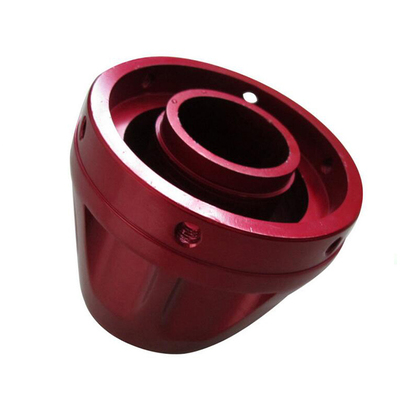
Toolpath generation is a central concern in cam profile CNC machining research. In a typical CNC milling operation, a rotating cutter removes material from a workpiece to form the cam’s contour. The toolpath—the trajectory of the cutter—must account for the tool’s geometry, including its diameter and cutting edge profile, to avoid overcutting or undercutting the desired shape. Early research focused on two-axis and three-axis machining, where the tool moves in the X-Y plane (for a plate cam) or X-Y-Z space (for a cylindrical cam). However, complex cams, such as roller gear cams or drum cams, often require multi-axis machining—typically four- or five-axis—to achieve the necessary precision. Five-axis CNC machines, with their ability to tilt and rotate the tool or workpiece, allow for continuous contact between the cutter and the cam surface, reducing errors and improving surface quality.
A notable example of multi-axis cam machining research is the work on roller gear cams, which are used in precision mechanisms like automatic tool changers (ATCs) in machine tools. In a 2009 study published on ResearchGate, authors explored the five-axis CNC machining of roller gear cams, emphasizing the development of specialized CAD/CAM software. Unlike plate cams, roller gear cams feature a helical or spiral groove that engages rollers on a follower shaft, requiring precise control of the tool’s orientation. The study highlighted the limitations of commercial CAM systems, which lacked tailored post-processing capabilities for such geometries, and proposed a custom software solution. Experimental results demonstrated good consistency between the designed and machined profiles, validating the approach for industrial applications.
Surface finish quality is another critical area of investigation. The cam-follower interface demands a smooth surface to minimize friction and wear, which directly affects the longevity and performance of the mechanism. CNC machining parameters—such as cutting speed, feed rate, and depth of cut—significantly influence surface roughness. Research has shown that high-speed machining (HSM), characterized by elevated spindle speeds and shallow cuts, can enhance surface quality by reducing tool vibration and thermal distortion. Adaptive toolpaths, which adjust the feed rate based on material removal rates, further optimize this process. For instance, trochoidal milling—a technique involving circular tool motions—has been adapted for cam profile machining to maintain consistent chip loads and improve finish.
Material selection and behavior under machining conditions also play a vital role in research efforts. Cams are commonly made from metals such as steel, aluminum, or cast iron, though advanced applications may use composites or ceramics. Each material presents unique challenges: steel requires robust tools to handle its hardness, while aluminum’s ductility can lead to burr formation. Research into tool materials, such as carbide or diamond-coated cutters, has improved machining outcomes by enhancing tool life and precision. Additionally, finite element analysis (FEA) is often employed to simulate material deformation and stress during machining, informing parameter optimization. A study examining the machining of SCM415 steel (a chromium-molybdenum alloy) for cam profiles used FEA to assess tool load effects, demonstrating how computational modeling complements experimental work.
The evolution of CAM software has been instrumental in advancing cam profile CNC machining. Early systems required manual input of G-code—a low-level programming language that instructs CNC machines—making the process labor-intensive and error-prone. Modern CAM software automates G-code generation by interpreting CAD models and applying preprogrammed machining strategies. Feature-based machining, a technique where the software recognizes geometric features (e.g., pockets or contours) and assigns appropriate toolpaths, has streamlined programming for cam profiles. Companies like Siemens (NX CAM), Autodesk (Fusion 360), and Mastercam have developed solutions that support multi-axis machining and real-time simulation, allowing operators to visualize the process and detect potential collisions before cutting begins.
Simulation and verification are indispensable in cam profile research. Virtual machining environments replicate the physical process, enabling researchers to test toolpaths, predict surface outcomes, and optimize parameters without wasting material. HyperMILL’s VIRTUAL Machining module, for example, uses generated NC code rather than internal CAM data for simulation, ensuring high fidelity to the actual machining process. This capability is particularly valuable for complex cams, where small deviations can disrupt follower motion. Experimental validation often follows simulation, with machined cams measured using coordinate measuring machines (CMMs) to assess geometric accuracy against design specifications.
The economic implications of cam profile CNC machining research are significant, particularly for small- and medium-batch production. Traditional methods, such as form grinding or manual milling, are cost-prohibitive for low volumes due to setup times and tooling costs. CNC machining, with its ability to rapidly switch between profiles via software, offers a cost-effective alternative. Research into adaptive manufacturing systems—where machines adjust parameters in real-time based on sensor feedback—promises further efficiency gains. For instance, integrating augmented reality (AR) into CNC workflows, as explored in recent Industry 4.0 studies, allows operators to visualize toolpaths overlaid on the workpiece, reducing errors and setup time.
Challenges persist in cam profile CNC machining, driving ongoing research. One issue is the trade-off between machining speed and accuracy: higher speeds can compromise surface finish, while slower speeds increase production time. Thermal effects from cutting also pose problems, as heat buildup can distort the workpiece or tool, necessitating coolant strategies or dry machining techniques. For complex cams, such as those with undercuts or steep gradients, tool accessibility remains a hurdle, often requiring custom fixtures or advanced machine configurations. Researchers are addressing these challenges through innovations like hybrid manufacturing—combining additive and subtractive processes—or machine learning algorithms that predict optimal machining conditions.
Applications of cam profile CNC machining span numerous industries. In automotive engineering, camshafts for high-performance engines demand profiles that maximize valve lift and timing precision. Aerospace systems use cams in actuators and control mechanisms, where lightweight materials and tight tolerances are critical. Medical devices, such as surgical robots, rely on miniature cams machined with extreme accuracy. The versatility of CNC technology, bolstered by research advancements, ensures its relevance across these domains, adapting to evolving design requirements and material innovations.
Future directions in cam profile CNC machining research are likely to emphasize sustainability and automation. Efforts to reduce energy consumption and material waste align with global manufacturing trends, prompting studies into eco-friendly cutting fluids and optimized toolpaths. Automation, driven by artificial intelligence (AI) and the Internet of Things (IoT), could enable fully autonomous cam production, with machines self-correcting based on real-time data. Collaborative robots (cobots) may also play a role, assisting human operators in setup and inspection tasks. As computational power grows, so too will the complexity of cam designs that CNC systems can handle, pushing the boundaries of mechanical engineering.
In conclusion, the research of cam profile CNC machining encapsulates a rich interplay of theory, technology, and application. From its roots in numerical control to its current status as a cornerstone of precision manufacturing, this field has evolved through rigorous scientific inquiry and engineering innovation. The development of advanced algorithms, multi-axis machining capabilities, and integrated CAD/CAM systems has transformed how cams are designed and produced, meeting the demands of modern machinery with unprecedented accuracy and efficiency. As research continues to address challenges and explore new frontiers, cam profile CNC machining will remain a vital area of study, shaping the future of mechanical systems across industries.
Reprint Statement: If there are no special instructions, all articles on this site are original. Please indicate the source for reprinting:https://www.cncmachiningptj.com/,thanks!
 3, 4 and 5-axis precision CNC machining services for aluminum machining, beryllium, carbon steel, magnesium, titanium machining, Inconel, platinum, superalloy, acetal, polycarbonate, fiberglass, graphite and wood. Capable of machining parts up to 98 in. turning dia. and +/-0.001 in. straightness tolerance. Processes include milling, turning, drilling, boring, threading, tapping, forming, knurling, counterboring, countersinking, reaming and laser cutting. Secondary services such as assembly, centerless grinding, heat treating, plating and welding. Prototype and low to high volume production offered with maximum 50,000 units. Suitable for fluid power, pneumatics, hydraulics and valve applications. Serves the aerospace, aircraft, military, medical and defense industries.PTJ will strategize with you to provide the most cost-effective services to help you reach your target,Welcome to Contact us ( sales@pintejin.com ) directly for your new project.

- 5 Axis Machining
- Cnc Milling
- Cnc Turning
- Machining Industries
- Machining Process
- Surface Treatment
- Metal Machining
- Plastic Machining
- Powder Metallurgy Mold
- Die Casting
- Parts Gallery
- Auto Metal Parts
- Machinery Parts
- LED Heatsink
- Building Parts
- Mobile Parts
- Medical Parts
- Electronic Parts
- Tailored Machining
- Bicycle Parts
- Aluminum Machining
- Titanium Machining
- Stainless Steel Machining
- Copper Machining
- Brass Machining
- Super Alloy Machining
- Peek Machining
- UHMW Machining
- Unilate Machining
- PA6 Machining
- PPS Machining
- Teflon Machining
- Inconel Machining
- Tool Steel Machining
- More Material