Mirroring Sheet Metal Parts in SOLIDWORKS
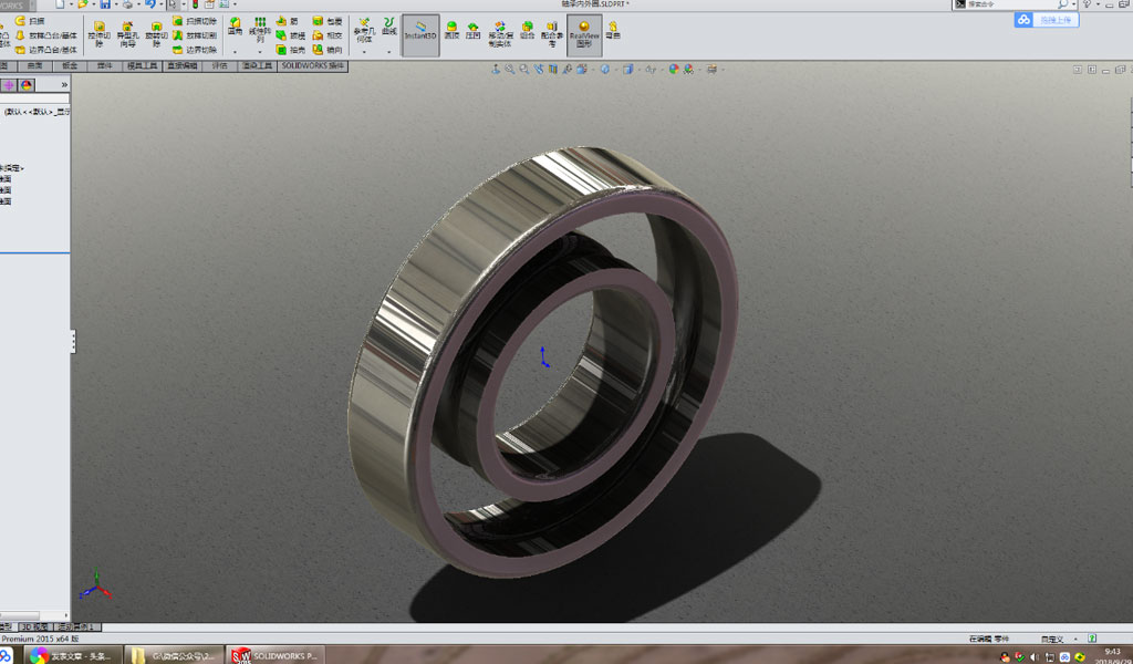
In SOLIDWORKS, a comprehensive 3D CAD software, the process of mirroring parts is a powerful feature that allows designers to create symmetrical parts efficiently. When it comes to sheet metal parts, mirroring not only saves time but also ensures consistency in design and manufacturing processes. This article provides an in-depth guide on how to mirror a sheet metal part in SOLIDWORKS, including the considerations and best practices to follow.
Overview of Sheet Metal in SOLIDWORKS
Sheet metal design in SOLIDWORKS is tailored for the specific requirements of manufacturing processes, such as bending, cutting, and forming. The software provides a suite of tools that allows users to create sheet metal parts with specific thicknesses, bend allowances, reliefs, and more. Understanding the unique characteristics of sheet metal in SOLIDWORKS is essential before undertaking operations like mirroring.
Mirroring Concepts in SOLIDWORKS
Mirroring in SOLIDWORKS involves creating a symmetrical copy of a part or feature about a plane or face. This function can be applied to features, bodies, or entire parts. In the context of sheet metal, mirroring can be used to duplicate complex bends, flanges, and other features without manually recreating them.
There are different types of mirroring operations in SOLIDWORKS:
- Feature Mirror: Mirrors individual features across a plane.
- Body Mirror: Mirrors entire solid bodies across a plane.
- Part Mirror: Creates a new, mirrored version of the entire part.
- Face Mirror: Mirrors selected faces across a plane or face.
Steps to Mirror a Sheet Metal Part in SOLIDWORKS
1. Preparing the Part for Mirroring
Before mirroring a sheet metal part, it is essential to ensure that the part is fully defined and that any necessary features or sketches are complete. If the part includes features like flanges, hems, or louvers, these should be finalized before initiating the mirroring process.
2. Selecting the Mirror Plane
The first step in the mirroring process is to select or create the plane about which the part will be mirrored. The plane can be one of the default planes (Front, Top, or Right), an existing face, or a custom plane created specifically for the operation.
- Default Planes: These are the planes that are automatically generated when starting a new part in SOLIDWORKS.
- Face Selection: If mirroring about an existing face, select the appropriate face on the part.
- Custom Plane: If the mirror operation requires a specific orientation, a new reference plane can be created using the "Plane" feature in SOLIDWORKS.
3. Mirroring Features or Bodies
Once the mirror plane is established, the next step is to select the type of mirroring operation.
-
Feature Mirror: To mirror individual features (e.g., a flange or cut), select "Mirror" from the Features toolbar. In the Mirror PropertyManager, choose the features to be mirrored and select the mirror plane. The software will generate the mirrored features automatically.
-
Body Mirror: To mirror an entire body, select "Mirror" and choose the body to be mirrored in the "Bodies to Mirror" section of the PropertyManager. The result will be a complete, mirrored version of the sheet metal body.
4. Mirroring the Entire Part
For a comprehensive mirror of the entire part, a different approach is taken:
- Insert Mirror Part: This method creates a new part that is a mirrored version of the original. To do this, go to the "Insert" menu, choose "Mirror Part," and select the appropriate plane. The software will prompt you to choose which features and bodies to include in the mirrored part.
This method is particularly useful when the mirrored part will be used as a separate component in an assembly. The mirrored part can retain links to the original, allowing for updates if the original part changes.
Considerations When Mirroring Sheet Metal Parts
While mirroring is a straightforward operation in SOLIDWORKS, certain considerations must be kept in mind, particularly for sheet metal parts:
-
Sheet Metal Parameters: Ensure that the sheet metal parameters (such as thickness, bend radius, and K-factor) are consistent before and after mirroring. Inconsistent parameters can result in issues during flattening or manufacturing.
-
Bend Alignment: When mirroring features that include bends, ensure that the bend alignment remains consistent with the original design intent. Misaligned bends can lead to inaccuracies in the final part.
-
Manufacturability: While SOLIDWORKS allows for the easy creation of mirrored parts, it is crucial to consider the manufacturability of the mirrored design. Certain configurations may not be feasible with the available manufacturing processes.
-
Drawing Updates: After mirroring, ensure that any associated drawings are updated to reflect the mirrored design. This is particularly important if the part is being used in assemblies or larger projects.
Best Practices for Mirroring Sheet Metal Parts
To ensure the best results when mirroring sheet metal parts in SOLIDWORKS, the following best practices should be followed:
-
Finalize Design Before Mirroring: Make sure the original part is fully designed and tested before performing the mirror operation. This minimizes the risk of needing to make changes to the mirrored part later.
-
Check Flattened States: After mirroring, verify that the flattened version of the sheet metal part is correct. This is crucial for generating accurate flat patterns for manufacturing.
-
Use Configurations for Variations: If different mirrored versions of a part are needed, consider using configurations. This allows for easy management of multiple mirrored versions within the same part file.
-
Utilize Symmetry: In cases where symmetry is a critical aspect of the design, use the symmetry feature in SOLIDWORKS to ensure that the mirrored part perfectly matches the original.
Conclusion
Mirroring sheet metal parts in SOLIDWORKS is an effective way to create symmetrical designs, saving both time and effort in the design process. By following the steps and best practices outlined in this article, designers can ensure that their mirrored parts are accurate, manufacturable, and consistent with the original design intent. Whether working on simple components or complex assemblies, mastering the mirroring process is a valuable skill for any SOLIDWORKS user.
Reprint Statement: If there are no special instructions, all articles on this site are original. Please indicate the source for reprinting:https://www.cncmachiningptj.com/,thanks!
 3, 4 and 5-axis precision CNC machining services for aluminum machining, beryllium, carbon steel, magnesium, titanium machining, Inconel, platinum, superalloy, acetal, polycarbonate, fiberglass, graphite and wood. Capable of machining parts up to 98 in. turning dia. and +/-0.001 in. straightness tolerance. Processes include milling, turning, drilling, boring, threading, tapping, forming, knurling, counterboring, countersinking, reaming and laser cutting. Secondary services such as assembly, centerless grinding, heat treating, plating and welding. Prototype and low to high volume production offered with maximum 50,000 units. Suitable for fluid power, pneumatics, hydraulics and valve applications. Serves the aerospace, aircraft, military, medical and defense industries.PTJ will strategize with you to provide the most cost-effective services to help you reach your target,Welcome to Contact us ( sales@pintejin.com ) directly for your new project.
- 5 Axis Machining
- Cnc Milling
- Cnc Turning
- Machining Industries
- Machining Process
- Surface Treatment
- Metal Machining
- Plastic Machining
- Powder Metallurgy Mold
- Die Casting
- Parts Gallery
- Auto Metal Parts
- Machinery Parts
- LED Heatsink
- Building Parts
- Mobile Parts
- Medical Parts
- Electronic Parts
- Tailored Machining
- Bicycle Parts
- Aluminum Machining
- Titanium Machining
- Stainless Steel Machining
- Copper Machining
- Brass Machining
- Super Alloy Machining
- Peek Machining
- UHMW Machining
- Unilate Machining
- PA6 Machining
- PPS Machining
- Teflon Machining
- Inconel Machining
- Tool Steel Machining
- More Material

